
TB 9-6625-2077-24
(6) Using measuring receiver and RF power measurement techniques; measured
power will indicate within the limits specified in table 5 for the TI RF OUTPUT
switch setting.
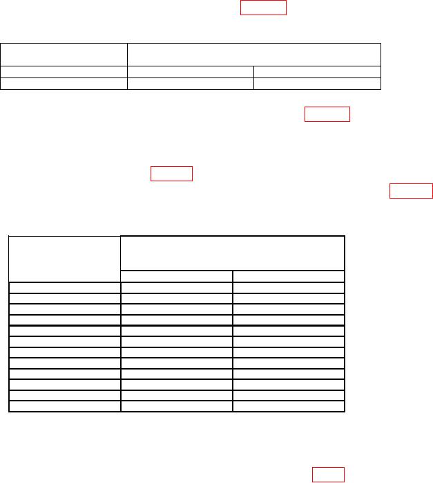
Table 5. Attenuation Accuracy
RF OUTPUT
Measuring receiver indications
switch
(dBm)
setting
Min
Max
10
9.000
11.000
(7) Set RF OUTPUT switch to the first value listed in table 6 and adjust RF
OUTPUT LEVEL control to the value indicated for the RF OUTPUT switch setting on
the TI RF OUTPUT meter.
(8) Set measuring receiver to measure tuned RF level; verify the measuring receiver
indicates within the limits specified in table 6 for the TI RF OUTPUT switch setting.
(9) Repeat technique of (7) and (8) above for remaining settings listed in table 6.
measuring receiver will be within limits specified.
Table 6. Attenuation Accuracy (Tuned Level)
Measuring receiver
RF OUTPUT
indications
switch
(dBm)
settings
Min
Max
0
-1.000
+1.000
-10
-9.000
-11.000
-20
-19.000
-21.000
-30
-29.000
-31.000
-40
-39.000
-41.000
-50
-49.000
-51.000
-60
-59.000
-61.000
-70
-69.000
-71.000
-80
-79.000
-81.000
-90
-89.000
-91.000
-100
-99.000
-101.000
-110
-108.000
-112.000
b. Adjustments
(1) Set POWER switch to OFF.
(2) Remove assembly A6 and reconnect using extender board (fig. 1).
(3) Set POWER switch to ON.
(4) Set RF OUTPUT switch to 0 dBm.
(5) Connect sensor module to the power reference output. Perform sensor zero
and calibration.
(6) Connect measuring receiver power sensor to TI RF OUTPUT and set
measuring receiver to measure power.
(7) Adjust RF OUTPUT LEVEL control for a +3.00 dBm indication on
measuring receiver.
8