
TB 9-6625-2094-24
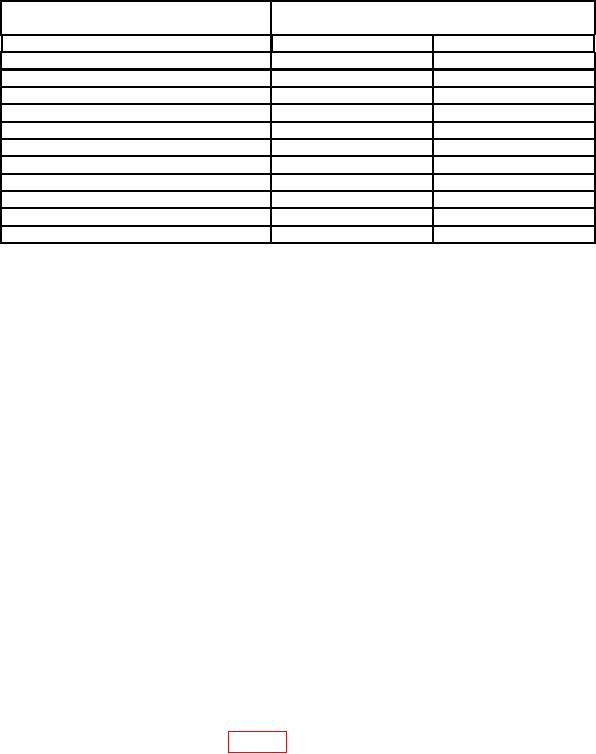
Table 5. Attenuator Accuracy
Test instrument step attenuator
Receiver system indications (dB)
settings
Min
Max
-10
-9.3
-10.7
-20
-19.3
-20.7
-301
-29.3
-30.7
-40
-39.3
-40.7
-50
-49.3
-50.7
-60
-59.3
-60.7
-701
-68.5
-71.5
-80
-78.5
-81.5
-90
-88.5
-91.5
-100
-98.5
-101.5
-110
-108.5
-111.5
1If
RCAL annunciator is illuminated, press the CAL key on the measuring receiver.
b. Adjustments. No adjustments can be made.
13. Amplitude Modulation Accuracy
a. Performance Check
NOTE
If necessary, ZERO and CALIBRATE measuring receiver and
sensor module.
(1) Connect measuring receiver sensor module to TI RF OUTPUT.
(2) Set measuring receiver to measure modulation rate.
(3) Position controls as listed in (a) through (f) below:
FREQUENCY switches to indicate 520.000 MHz.
(a)
MODULATION MODE switch to AM.
(b)
MODULATION FREQ switch to 400 Hz.
(c)
MODULATION FM/AM slide control to 90 percent.
(d)
OUTPUT step attenuator switch for 0 dBm.
(e)
OUTPUT VERNIER control for -3 dB.
(f)
(4) The measuring receiver will indicate between 380 and 420 Hz modulation.
(5) Set MODULATION FREQ switch to 1 kHz.
(6) The measuring receiver will indicate between 950 and 1050 Hz modulation.
(7) Set measuring receiver to measure AM. If measuring receiver does not indicate
within limits specified in first row of table 6, perform b below.