
TB 9-6625-2094-24
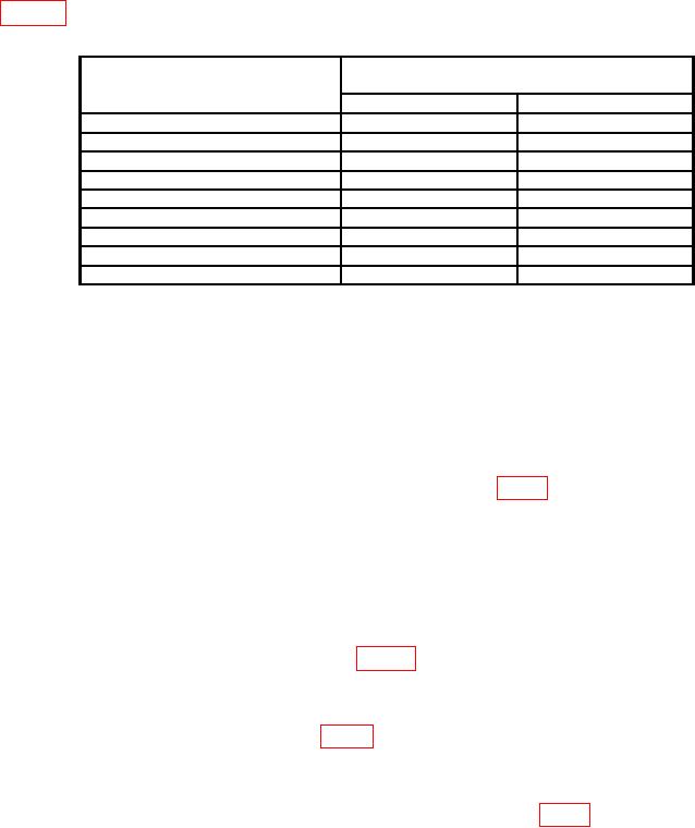
(8) Repeat technique of (3) (d) above for TI OUTPUT percent settings listed in
table 6. Measuring receiver will indicate within limits specified.
Table 6. Amplitude Modulation
Test instrument (MODULATION
Measuring receiver percent modulation
FM/AM) percent slide settings
(AM)
Min
Max
90%
81.0
99.0
80%
71.5
88.5
70%
62.0
78.0
60%
52.5
67.5
50%
43.0
57.0
40%
33.5
46.5
30%
24.0
36.0
20%
14.5
25.5
10%
5.00
15.0
b. Adjustments
(1) Position controls as listed in (a) through (e) below:
FREQUENCY switches to 520.000 MHz.
(a)
MODULATION MODE switch to AM.
(b)
MODULATION FREQ switch to DC.
(c)
OUTPUT step attenuator switch for 0 dBm.
(d)
OUTPUT VERNIER control for +3 dB.
(e)
(2) Connect audio analyzer INPUT HI to MOD TP (fig. 1) and chassis ground.
NOTE
Set audio analyzer to read V dc.
(3) Adjust MODULATION FM/AM slide control until audio analyzer indicates 4.5 V dc.
(4) Set MOD FREQ to 1000 Hz.
(5) Connect measuring receiver sensor module to TI RF OUTPUT.
(6) Adjust meter board POT G (fig. 2) for 90 percent AM indication on the
measuring receiver modulation display (R).
(7) Set OUTPUT VERNIER control for -7 dBm indication on OUTPUT meter.
(8) Adjust meter board POT H (fig. 2) for 90 percent AM indication on the measuring
receiver modulation display (R).
(9) Repeat technique above until no further adjustment is required.
(10) Disconnect audio analyzer INPUT HI from MOD TP (fig. 1) and chassis ground.
14