
TB 9-6625-2099-24
(31) Remove 50 feedthrough termination from oscilloscope calibrator CHAN 2 and
TI CH 2. Reconnect oscilloscope calibrator CHAN 2 to TI CH 2 using a 5-80 pF
standardizer. Rotate oscilloscope calibrator knob located below EDIT FIELD pushbutton
to obtain 6 divisions 6 divisions of vertical display.
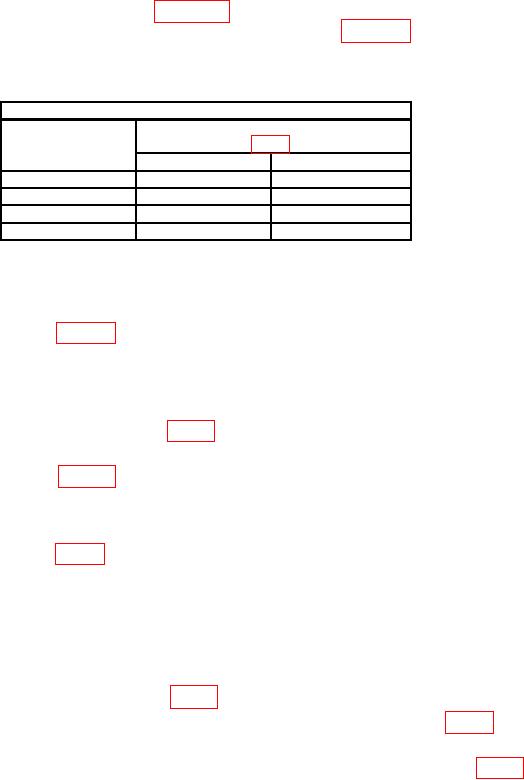
(32) Adjust oscilloscope calibrator output for 6 divisions of display at each
VOLTS/DIV switch setting listed in table 10. If oscilloscope does not display square
corners and flat tops, perform appropriate adjustments listed in table 10.
(33) Remove 5-80 pF standardizer from oscilloscope calibrator CHAN 2 and TI CH 2.
Table 10. Attenuator Compensation
Test instrument
CH 1 and CH 2 adjustments
VOLTS/DIV
switch settings
Square corners
Flat top
20
mV
C106
C107
50
mV
C110
C111
0.1 mV
C114
C115
1
V
C118
C119
1Adjustments
for CH 1 and CH 2 are numbered the same.
b. Adjustments
(1) Ensure oscilloscope calibrator output and TI VOLTS/DIV switch setting is set
as indicated in first row of table 8.
(2) Adjust CH 1 GAIN (front panel) for 4 divisions of amplitude.
(3) Set CH 1 VOLTS/DIV switch to 10 mV and oscilloscope calibrator output for 50
mV.
(4) Adjust R1317 CH 1 2X GAIN (fig. 3) for 5 divisions of amplitude (R).
(5) Ensure oscilloscope calibrator output and TI VOLTS/DIV switch setting is set
as indicated in first row of table 9.
(6) Adjust CH 2 GAIN control (front panel) for 4 divisions of amplitude.
(7) Set CH 2 AC-GND-DC switch to AC.
(8) Adjust R2411 (fig. 3) polarity gain for minimum gain change while switching
CH 2 POLARITY switch between +UP and INVERT.
(9) Set CH 2 AC-GND-DC switch to DC and repeat (6) through (8) above until no
further adjustments are needed.
(10) Set CH 2 AC-GND-DC switch DC and VOLTS/DIV switch to 10 mV.
(11) Set oscilloscope calibrator output controls for 50 mV at 1 kHz.
(12) Adjust R2317 CH 2 2X GAIN (fig. 3) for 5 divisions of amplitude (R).
(13) Adjust LF R1436 and R1431 (LF R1436 for SN 159999 and below) (fig. 3) for
best flat top (minimum tilt) (R).
(14) Adjust LF R2436 and HF R2431 (LF R2436 for SN 159999 and below) (fig. 3) for
best flat top (minimum tilt) (R).
14