
TB 9-6625-2102-24
(b) Adjust TI VARIABLE control to settings.
(c) Using oscilloscope, verify frequency duty cycle.
NOTE
All out-of-tolerance indications, perform b below:
Table 5. Frequency Symmetry
Test instrument
Oscilloscope duty cycle
indications
FREQ/PERIOD MULT
(%)
(Hz/s)
VARIABLE
Switch
Min
Max
settings
control fully
10/1k
cw
49
51
-
ccw
49
51
1K/100K
ccw
49
51
-
cw
45
55
(9) Disconnect TI from oscilloscope.
b. Adjustments
(1) Connect TI MODULATION GENERATOR OUT (600 :) to audio analyzer
INPUT HIGH.
(2) Set up audio analyzer to measure frequency.
(3) Set FREQ/PERIOD MULT (Hz/s) switch to 1K/100K and adjust VARIABLE
control fully cw.
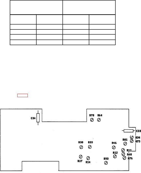
(4) Adjust R48 (fig 1) until audio analyzer indicates between 100.0 and 100.4 kHz (R).
Figure 1. Test instrument top view.
(5) Adjust VARIABLE control fully ccw.
6