
TB 9-6625-2102-24
(6) Set MODULATION GENERATOR FUNCTION switch to
. If audio
analyzer does not indicate within limits in table 8, perform b (3) below.
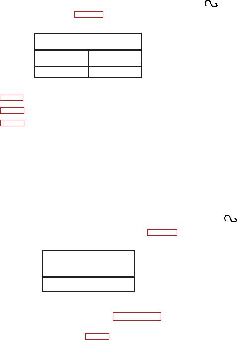
Table 8. Sine Wave Zero
Audio analyzer indications
(DC V)
Min
Max
- 0.010
+ 0.010
b. Adjustments
(1) Adjust R34 (fig. 1) for minimum indication less 10 mV on audio analyzer (R).
(2) Adjust R33 (fig. 1) for minimum indication less 10 mV on audio analyzer (R).
(3) Adjust R76 (fig. 1) for minimum indication less 10 mV on audio analyzer (R).
10. Modulation Generator Distortion
a. Performance Check
(1) Ensure audio analyzer is connected to MODULATION GENERATOR OUT (600:).
(2) Set up audio analyzer to measure distortion.
(3) Ensure MODULATION GENERATOR, FREQ/PERIOD MULT (Hz/s) switch
is set to 10/1K and adjust VARIABLE control fully cw.
(4) Ensure MODULATION GENERATOR, FUNCTION switch is set to
.
(5) If audio analyzer does not indicate within limits in table 9, perform b below.
Table 9. Distortion Accuracy
Audio analyzer distortion
indications
(<%)
5
NOTE
If adjustments are made, repeat paragraph 9 above.
b. Adjustments. Adjust R11 and R12 (fig. 1) in increments for minimum distortion
less than 5 percent (R) on audio analyzer.
11. Modulation Generator Ramp
a. Performance Check
(1) Connect TI MODULATION GENERATOR OUT (600 :) to oscilloscope
Vertical 1 input.
(2) Set FREQ/PERIOD MULT (Hz/s) switch to 10/1k and adjust VARIABLE
control fully cw.