
TB 9-6625-2124-24
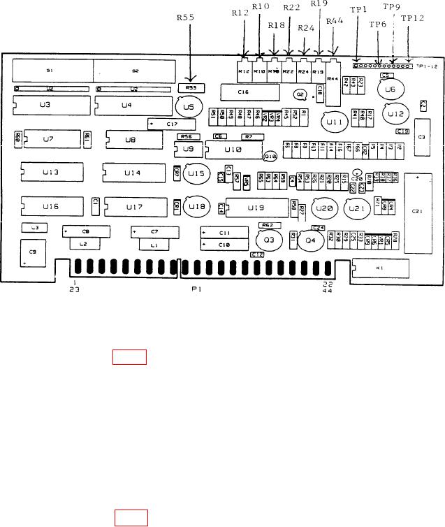
Figure 6. A8 board adjustment locations.
(8) The FREQUENCY display will indicate 2C83 and the FREQUENCY/TIME
display will indicate 00; if not, repeat (3) through (7) above.
(9) Adjust A8R22 (fig. 6) for multimeter indication of -7.000 V dc (R).
key two times. The FREQUENCY display will indicate 2C81.
(10) Press
(11) Press function keys and enter corresponding data on keyboard as listed in as
listed in (a) through (d) below:
key, DATA ENTRY 0 BKSP.
(a)
key, DATA ENTRY 0 BKSP.
(b)
key, DATA ENTRY 0 BKSP.
(c)
key, DATA ENTRY 0 BKSP.
(d)
(12) The FREQUENCY display will indicate 2C83 and the FREQUENCY/TIME
display will indicate 0F.
(13) Adjust A8R24 (fig. 6) for multimeter indication of -20.000 V dc (R).
(14) Repeat (10) above.
(15) Press function keys and enter corresponding data on keyboard as listed in as
listed in (a) through (d) below:
key, DATA ENTRY 0 BKSP.
(a)
key, DATA ENTRY 0 BKSP.
(b)
key, DATA ENTRY 0 BKSP.
(c)
24