
TB 9-6625-2124-24
23. Step Attenuator Accuracy (Option 002 only)
a. Performance Check
NOTE
Ensure proper calibration factors for sensor module being used
are loaded into measuring receiver.
(1) Connect measuring receiver to RF OUTPUT.
(2) Press function keys and enter corresponding data on keyboard as listed in (a)
and (b) below:
(a) CW key, DATA ENTRY 12 GHz.
(b) POWER LEVEL key, DATA ENTRY 0 dBm.
(3) Press RF ON/OFF key to ON and establish a reference on measuring receiver
at 12 GHz.
(4) Make POWER LEVEL data entries as listed in table 9. Using standard tuned
level measurement techniques, measured power will indicate within limits specified.
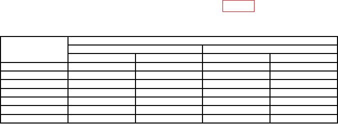
Table 9. Step Attenuator Setting
Test instrument
Measuring receiver indications (dB)
power level
12 GHz
18 GHz
data entries
Min
Max
Min
Max
-10
-9.4
-10.6
-9.3
-10.7
-20
-19.3
-20.7
-19.1
-20.9
-30
-29.1
-30.9
-28.8
-31.2
-40
-38.2
-41.8
-38.0
-42.0
-50
-48.0
-52.0
-47.7
-52.3
-60
-57.8
-62.2
-57.5
-62.5
-70
-67.7
-72.3
-67.2
-72.8
(5) Press function keys and enter corresponding data on keyboard as listed in (a)
and (b) below:
(a) CW key, DATA ENTRY 18 GHz.
(b) POWER LEVEL key, DATA ENTRY 0 dBm.
(6) Repeat (3) and (4) above at 18 GHz.
b. Adjustments. No adjustments can be made.
24. AM ON/OFF Ratio and Square Wave Symmetry
a. Performance Check
(1) Connect spectrum analyzer to RF OUTPUT, using 10 dB attenuator.
(2) Press function keys and enter corresponding data on keyboard as listed in (a)
through (d) below:
(a) INSTR PRESET key.
(b) CW key, DATA ENTRY 1 GHz.
(c) POWER LEVEL key, DATA ENTRY 10 dBm.