
TB 9-6625-2124-24
START key, DATA ENTRY 10 MHz.
(b)
STOP key, DATA ENTRY 18 GHz.
(c)
POWER LEVEL key, DATA ENTRY 10 dBm.
(d)
RF BLANK (ON).
(e)
(24) Set oscilloscope for an X verses Y operation and adjust controls as necessary to
display the TI output.
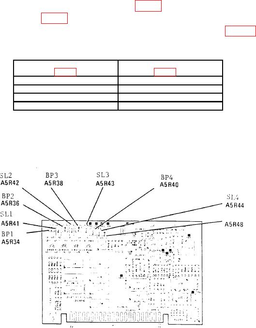
(25) Set A5R34, A5R36, A5R38, and A5R40 (fig. 12) fully cw.
(26) Adjust A5R48 (fig. 12) for best overall trace flatness as displayed on oscilloscope (R).
(27) Adjust BP (breakpoint) and SL (slope) adjustments listed in table 8 for best
overall trace flatness as displayed on oscilloscope.
Table 8. BP and SL Adjustments
BP adjustment
SL adjustments
(fig. 12) (R)
BP1 A5R34
SL1 A5R41
BP2 A5R36
SL2 A5R42
BP3 A5R38
SL3 A5R43
BP4 A5R40
SL4 A5R44
NOTE
The BP adjustment determines at what frequency the
corresponding SL adjustment takes effect.
Figure 12. A5 board adjustment locations.
36