
TB 9-6625-2124-24
CW key, DATA ENTRY 50 MHz.
(b)
POWER LEVEL key, DATA ENTRY -5 dBm.
(c)
SAVE key, DATA ENTRY 1.
(d)
CW key, DATA ENTRY 2.2 GHz.
(e)
SAVE key, DATA ENTRY 2.
(f)
POWER LEVEL key, DATA. ENTRY 3 dBm.
(g)
SAVE key, DATA ENTRY 3.
(h)
CW key, DATA ENTRY 50 MHz.
(i)
SAVE key, DATA ENTRY 4.
(j)
POWER LEVEL key, DATA ENTRY 10 dBm.
(k)
SAVE key, DATA ENTRY 5.
(l)
CW key, DATA ENTRY 2.2 GHz.
(m)
SAVE key, DATA ENTRY 6.
(n)
RECALL key, DATA ENTRY 1.
(o)
(3) Connect power meter to RF OUTPUT. Record power meter indication.
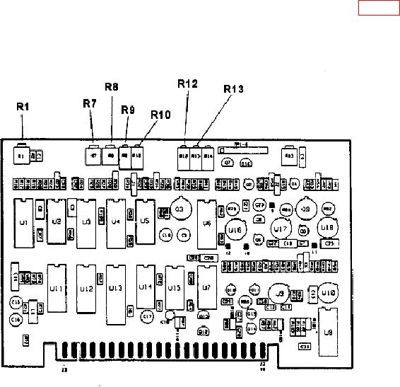
(4) Press RECALL key and enter data 2 on keyboard. Adjust A4R1 (fig. 11) for
power meter indication of equal difference from -5 dBm as the value recorded in (3) above
but in the opposite direction (example: if (3) above is -4.9 dBm then A4R1 is adjusted for
-5.1 dBm) (R).
Figure 11. A4 board adjustment locations.
34