
TB 9-6625-2124-24
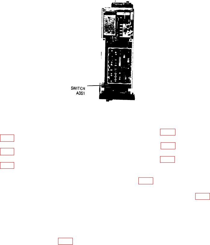
Figure 9. Switch A3S1 location.
(3) Press INSTR PRESET and CW keys. Enter data 20 GHz on keyboard.
(4) Adjust FREQUENCY VERNIER control for multimeter indication of 10.000 V dc.
(5) Disconnect multimeter from A6TP9 and connect to A6TP5 (fig. 7). Adjust A6R16
(fig. 7) for multimeter indication -10.000 V dc (R).
(6) Disconnect multimeter from A6TP5 and connect to A6TP4 (fig. 7). Adjust A6R21
(fig. 7) for multimeter indication of 0.000 V dc (R).
(7) Disconnect multimeter from A6TP4 and connect to A6TP8 (fig. 7). Adjust A6R34
(fig. 7) for multimeter indication of -10.000 V dc (R).
(8) Press CW key and enter data 13.5 GHz on keyboard.
(9) Connect multimeter to A6TP5 (+) and A6TP10 (-) (fig. 7).
(10) Adjust FREQUENCY VERNIER control for multimeter indication of -6.74837 V dc.
(11) Disconnect multimeter from A6TP5 and connect to A6TP8. Adjust A6R24 (fig. 7)
for multimeter indication of 0.000 V dc (R).
(12) Press CW key and enter data 7 GHz on keyboard.
(13) Disconnect multimeter from A6TP8 and connect to A6TP5.
(14) Adjust FREQUENCY VERNIER control for multimeter indication of -3.49675 V dc.
(15) Disconnect multimeter from A6TP5 and connect to A6TP8.
(16) Adjust A6R26 (fig. 7) for multimeter indication of 0.000 V dc.
(17) Press CW key and enter data 2.4 GHz on keyboard.
(18) Repeat (13) above.
(19) Adjust FREQUENCY VERNIER control for multimeter indication of -1.19560 V dc.
30