
TB 9-6625-2124-24
(20) Repeat (15) above.
(21) Adjust A6R28 (fig. 7) for multimeter indication of 0.000 V dc (R).
(22) Press CW key and enter data 10 MHz on keyboard.
(23) Repeat (13) above.
(24) Adjust FREQUENCY VERNIER control for multimeter indication of 0.00000 V dc.
(25) Repeat (15) above.
(26) Adjust A6R30 (fig. 7) for multimeter indication of 0.000 V dc (R).
Connect SWEEP OUTPUT to oscilloscope
(27) Disconnect multimeter from TI.
CH2 input.
(28) Connect oscilloscope CH1 input to A6TP8. Press INSTR PRESET key.
(29) Set oscilloscope as listed in (a) through (d) below:
CH1 VOLTS/DIV to .5.
(a)
CH2 VOLTS/DIV to .5.
(b)
CH1 input to DC.
(c)
CH2 input to DC.
(d)
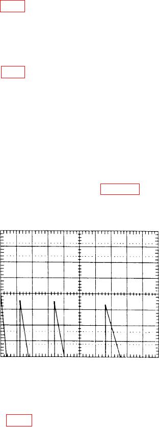
(30) Set oscilloscope for an X verses Y function operation and adjust oscilloscope
controls as required to obtain a display as shown in figure 10.
Figure 10. Oscilloscope display.
(31) Adjust oscilloscope CH1 POSITION control to align top of first ramp with
display horizontal center graticule line.
(32) Adjust A6R37 (fig. 7) to align the tops of the second, third, and fourth ramps
with the oscilloscope horizontal center graticule line (R).
(33) Return switch A3S1 position 1 to the CLOSED (down) position.
31