
TB 9-6625-2124-35
(7) Adjust synthesized signal generator frequency control to align the birdie with
the leading edge of M1 marker on oscilloscope display. Synthesized signal generator will
indicate between 0.850 and 1.150 GHz.
NOTE
If an out-of-tolerance condition is noted in (7) above or (8)
through (40) below, perform b below.
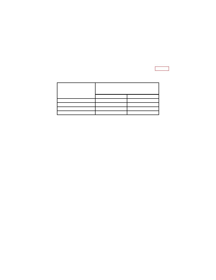
(8) Repeat technique of (6) and (7) above for TI markers listed in table 6.
Synthesized signal generator will indicate as specified.
Microwave measurement system
Test
indication
instrument
(GHz)
marker
Min
Max
M2
3.850
4.150
M3
7.850
8.150
M4
13.850
14.150
M5
16.850
17.150
(9) Adjust synthesized signal generator frequency control to align the birdie with
the end of TI sweep as indicated on oscilloscope display.
(10) Synthesized signal generator will indicate between 17.450 and 17.550 GHz.
(11) Press function keys and enter corresponding data on keyboard as listed in (a)
through (d) below:
(a)
START key, DATA ENTRY 10 MHz.
(b)
STOP key, DATA ENTRY 2.4 GHz.
(c)
M1 key, DATA ENTRY 1 GHz.
(d)
M2 key, DATA ENTRY 2 GHz.
(12) Repeat (6) above.
(13) Repeat technique of (7) above. Synthesized signal generator will indicate
between 0.974 and 1.026 GHz.
(14) Repeat technique of (6) and (7) above for M2 marker. Synthesized signal
generator will indicate between 1.974 and 2.026 GHz.
(15) Repeat (9) above.
(16) Synthesized signal generator will indicate between 2.385 and 2.415 GHz.
(17) Press function keys and enter corresponding data on keyboard as listed in (a)
through (j) below:
(a)
START key, DATA ENTRY 2.4 GHz.
(b)
STOP key, DATA ENTRY 7 GHz.
(c)
M1 key, DATA ENTRY 3 GHz.
(d)
M2 key, DATA ENTRY 6 GHz.
(e)
M3 key.
(f)
OFF key.
28
