TB 9-6625-2124-35
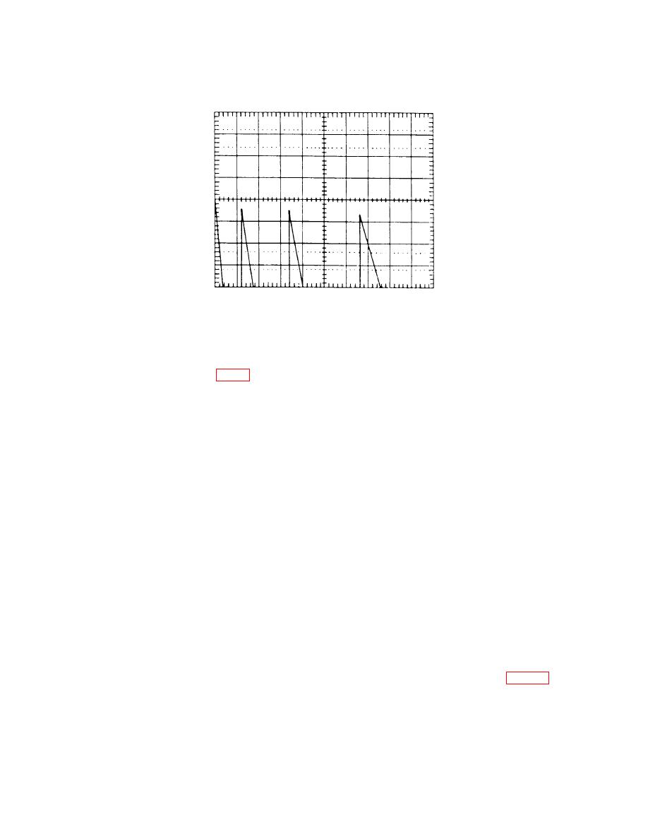
(31) Adjust oscilloscope CH1 POSITION control to align top of first ramp with
display horizontal center graticule line.
(32) Adjust A6R37 (fig. 7) to align the tops of the second, third, and fourth ramps
with the oscilloscope horizontal center graticule line (R).
(33) Return switch A3S1 position 1 to the CLOSED (down) position.
22. Output Power
a. Performance Check
(1) Press function keys and enter corresponding data on keyboard as listed in (a)
through (c) below:
(a) INSTR PRESET key.
(b) CW key, DATA ENTRY 50 MHz.
(c) POWER LEVEL key, DATA ENTRY 0.0 dBm.
NOTE
Values in parenthesis pertain to Option 002.
(2) Connect power meter to RF OUTPUT. Power meter will indicate 0.0 1.5 (1.7)
dBm; if not, perform b (1) through (20) below.
(3) Manually adjust power control for power meter indication of +10.0 dBm.
POWER display will indicate between 8.5 and 11.5 (8.3 and 11.7) dBm; if not, perform b (1)
through (20) below.
(4) Manually adjust power control for power display indications listed in table 7.
Power meter will indicate as specified; if not, perform b (1) through (20) below.
(5) Enter data 0 dBm on keyboard. Record power meter indication.


