
TB9-6625-2131-24
b. Adjustments
is aligned with horizontal graticule centerline (R).
(2) Adjust VERT CTR R1714 A13 until trace remains within 0.5 division of
horizontal graticule centerline while VERTICAL MODE switches are simultaneously
switched from BEAM 1 RIGHT and BEAM 2 LEFT, and while adjust BA714 for best
compromise (R).
(3) Adjust R2714 A16 (fig. 1) until trace remains within 0.5 division of horizontal
graticule centerline while VERTICAL MODE switches are simultaneously switched from
BEAM 2 RIGHT and BEAM 1 LEFT, and while adjusting R2714 for best compromise (R).
is aligned with horizontal graticule centerline (R).
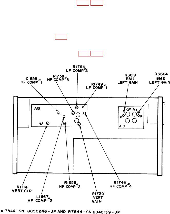
Figure 7. Test instrument - left side view.
15