TB9-6625-2131-24
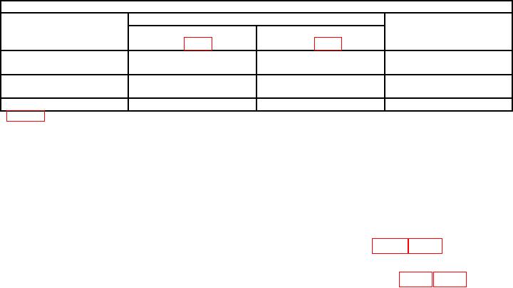
Table 5. High-Frequency Compensation
Test instrument
Adjustments (R)
Primary area of
Optimum
BEAM 1
BEAM 2
pulse affected
sweep rate
1
(A16 fig. 1)1
(A13 fig. 7)
10 nsec/div
HF COMP#4 R1743
HF COMP#4 R2743
First 100 nsec
HF COMP#5 R1758
HF COMP#5 R2758
2 nsec/div
HF COMP#3 L1667
HF COMP#3 L2667
First 2 nsec
HF COMP#1 C1658
HF COMP#1 C2658
2 nsec/div
HF COMP#2 R1658
HF COMP#2 R2658
First 5 nsec
Figure 8 for type R7844.
(7) Move standardizer to RIGHT VERT compartment, time base to B HORIZ
compartment and set BEAM 2 VERT MODE to RIGHT.
(8) Repeat (2) and (3) above. If pulse displayed on crt does not have flat top within
0.5 minor division, perform b (2) below.
(9) Repeat (4) and (5) above for beam 2.
b. Adjustments
R7844) for flat top within 0.5 minor division on crt.
type R7844) for flat top within 0.5 minor division on crt.
17. Vertical Amplifier 400 MHz Gain
a. Performance Check
(1) Set standardizer TEST switch to VERT or HORIZ FREQ RESP.
(2) Connect signal generator RF output to standardizer FREQ RESP input.
(3) Set time base sweep rate for .1 μs and set MODE switch to AUTO.
(4) Adjust signal generator frequency to 20 MHz and amplitude for 6 divisions of
display on crt.
(5) Center the display on crt, using time base and standardizer POSITION controls.
amplitude is reduced to 4.5 divisions. Signal generator will indicate 400 MHz or higher.
NOTE
Standardizer CW LEVELED light must be on in order to
obtain proper results in (6) above.
(7) Move standardizer to LEFT VERT compartment and time base to A HORIZ
compartment.
(8) Repeat (4) through (6) above.
NOTE
Do not perform (9) through (14) below if TI has option 21.

