
TB 9-6625-2138-24
a. Set switches as listed in (1) through (11) below:
(1) CLOCK to 9600.
(2) PATTERN to 1:1.
(3) EXPONENT RANGE to 2.
(4) SINGLE/CYCLE (PRINTER) to CYCLE (PRINTER).
(5) OFF/LOOP to LOOP.
(6) OFF/XMIT ERRORS to OFF.
(7) OFF/FILTER to OFF.
(8) EVENT to JITTER/TOTAL PEAK.
(9) JITTER/TOTAL PEAK to JITTER.
(10) DATA-DATA to DATA.
(11) DTR/RTS/BACKWARD CHANNEL to DTR.
b. Connect autotransformer to a 115 V ac source and adjust for 115 V.
c. Connect TI to autotransformer.
d. Set LINE OFF-ON switch to ON and allow at least 3 minutes for warm-up and
stabilization.
8. Phase Lock Loop
a. Performance Check
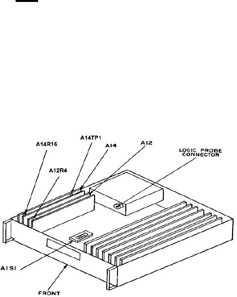
(1) Remove TI top cover and connect oscilloscope to A14TP1 (fig. 1).
Figure 1. Test instrument - top view.