
TB 9-6625-2138-24
10. Transmit Pattern
a. Performance Check
(1) Set TI as listed in (a) through (g) below:
CLOCK to 9600.
(a)
EXPONENT RANGE to AUTO.
(b)
SINGLE/CYCLE (PRINTER on some models) to SINGLE.
(c)
OFF/LOOP to OFF.
(d)
OFF/XMIT ERRORS to XMIT ERRORS.
(e)
EVENT to BIT ERROR.
(f)
COUNT D/O COUNT C/L switch to COUNT C/L.
(g)
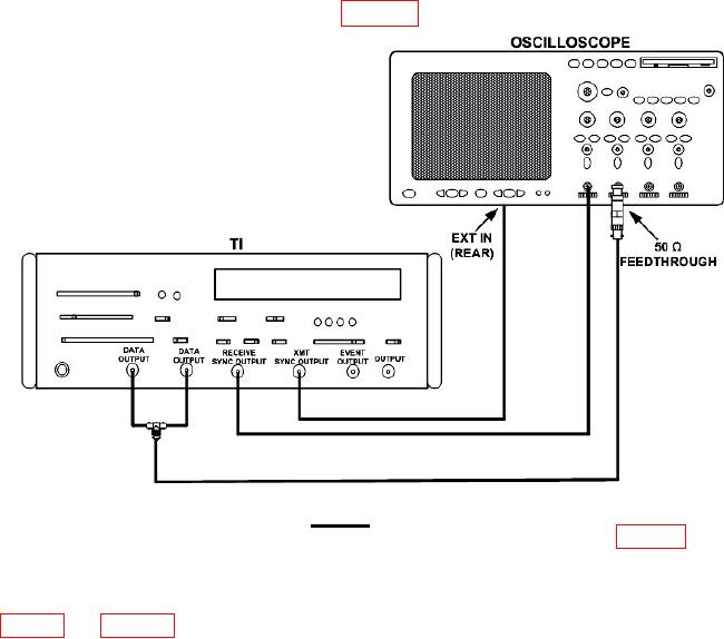
(2) Connect equipment as shown in figure 2.
Figure 2. Transmit - equipment setup.
(3) Set PATTERN and DATA/DATA switches to settings listed in table 4. At each
setting momentarily set START/STOP switch to START. Observe that TEST ON
indicator is on while readout is counting, and then goes out when counting stops. After
TEST ON indicator goes out, observe that readout and oscilloscope indications are as listed