
TB 9-6625-2138-24
(11) Set LINE switch to ON.
(12) Connect multimeter between pin 4 of A15J1 connector on rear panel and chassis
ground. Multimeter indication will be between -5 and -12 V.
(13) Set DTR/RTS/BACKWARD CHANNEL switch to BACKWARD CHANNEL.
Multimeter indication will be between +5 and +12 V.
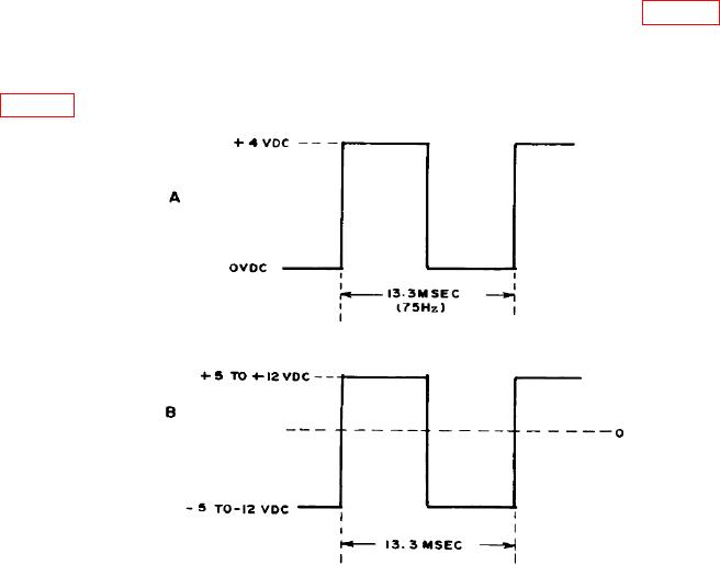
(14) Adjust pulse generator for oscilloscope indication as shown in figure 5A, and
connect pulse generator output to BACKWARD CHANNEL DATA connector (rear panel).
(15) Connect oscilloscope between pin 14 of A15J1 connector on rear panel (RS232C
DATA INTERFACE) and chassis ground. Oscilloscope indication will be as shown in
Figure 5. Dropout waveforms.
(16) Remove top cover and set COUNT D/O COUNT C/L switch to COUNT D/O.
Replace cover.
b. Adjustments. No adjustments can be made.
13. Power Supply
NOTE
Do not perform power supply check if all other parameters are
within tolerance.