
TB 9-6625-2164-35
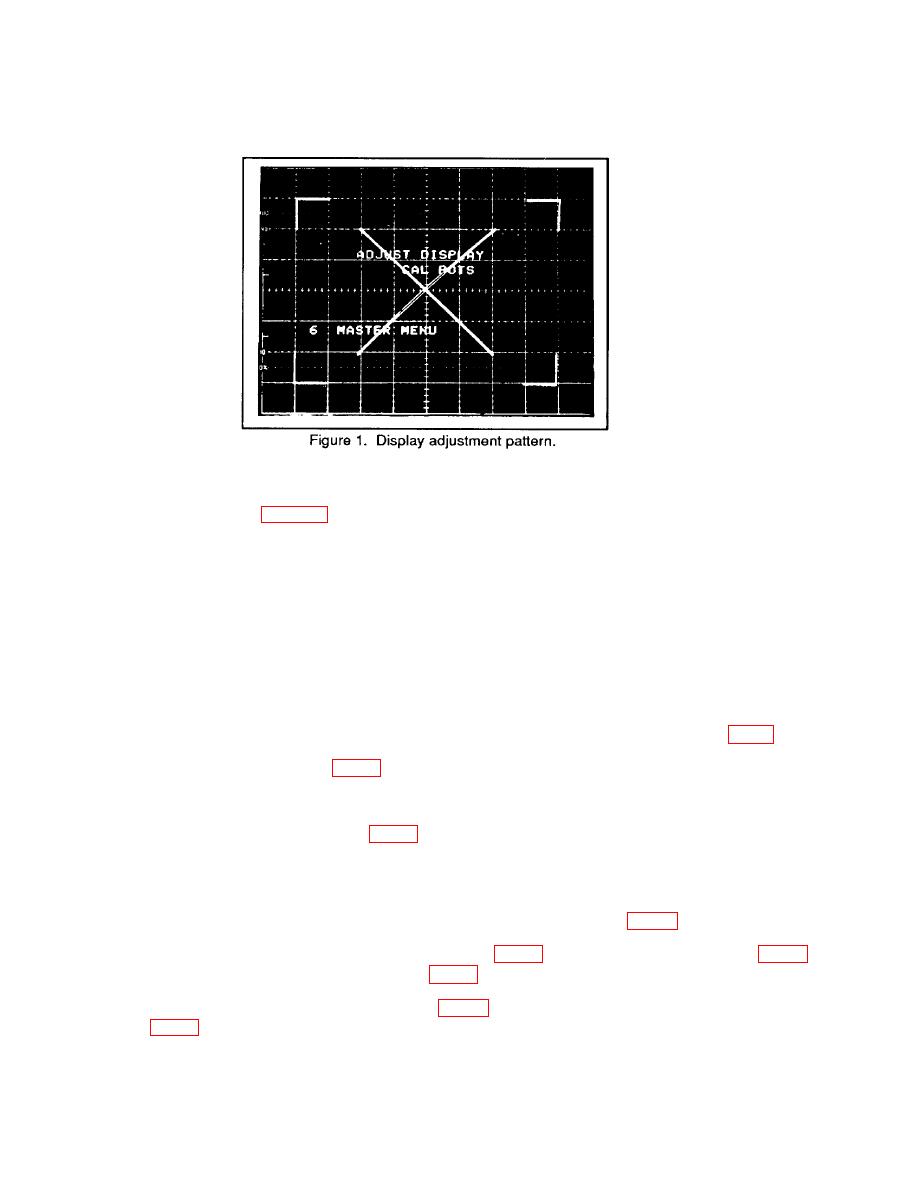
g. Adjust VECT LIN for minimum trace separation of the diagonal lines on the display
pattern as shown in figure 1.
h. Press MEMORY DISPLAY/6 and MENU/TEST pushbuttons. MASTER MENU
will clear display.
i. Press MENU/TEST and MEMORY DISPLAY 4, 5, 6 and MENU/TEST pushbuttons.
j.
Press TRIGGERING/MODE AUTO pushbutton.
k. Press TRIGGERING/COUPLING AC pushbutton.
Press TRIGGERING/SOURCE EXT pushbutton.
l.
o. Press TRIGGERING/COUPLING DC pushbutton.
q. Press AQR MODE/BOTH pushbutton and position CH 1 and CH 2 POSITION
controls to the center graticule line.
and adjust CH 1 TRIGGER OFFSET R518, (fig. 4) for 0 V 2 mV dc on multimeter.
GND (fig. 4).
5
