
TB 9-6625-2173-35
(3) Adjust TRIGGERING LEVEL, CH1
HORIZONTAL
POSITION
and
TIME/DIV controls for a stable, centered display.
(4) Adjust CH1 VOLTS/DIV and VAR control for 6 divisions of vertical deflection
on TI.
(5) Remove connection at TI CALIBRATOR and connect oscilloscope calibrator
SOURCE/MEASURE CHAN 1 to TI CH1 (do not change setting set in (4) above).
(6) Set oscilloscope calibrator VOLTAGE output to 600 mV, 1 kHz.
(7) Rotate oscilloscope calibrator EDIT FIELD knob to adjust for 6 divisions of
vertical deflection on TI. Oscilloscope calibrator err display will indicate within 1%, if not,
perform b below.
b. Adjustments
(1) Connect digital multimeter HI to TI CAL 0.6V and LO to chassis ground.
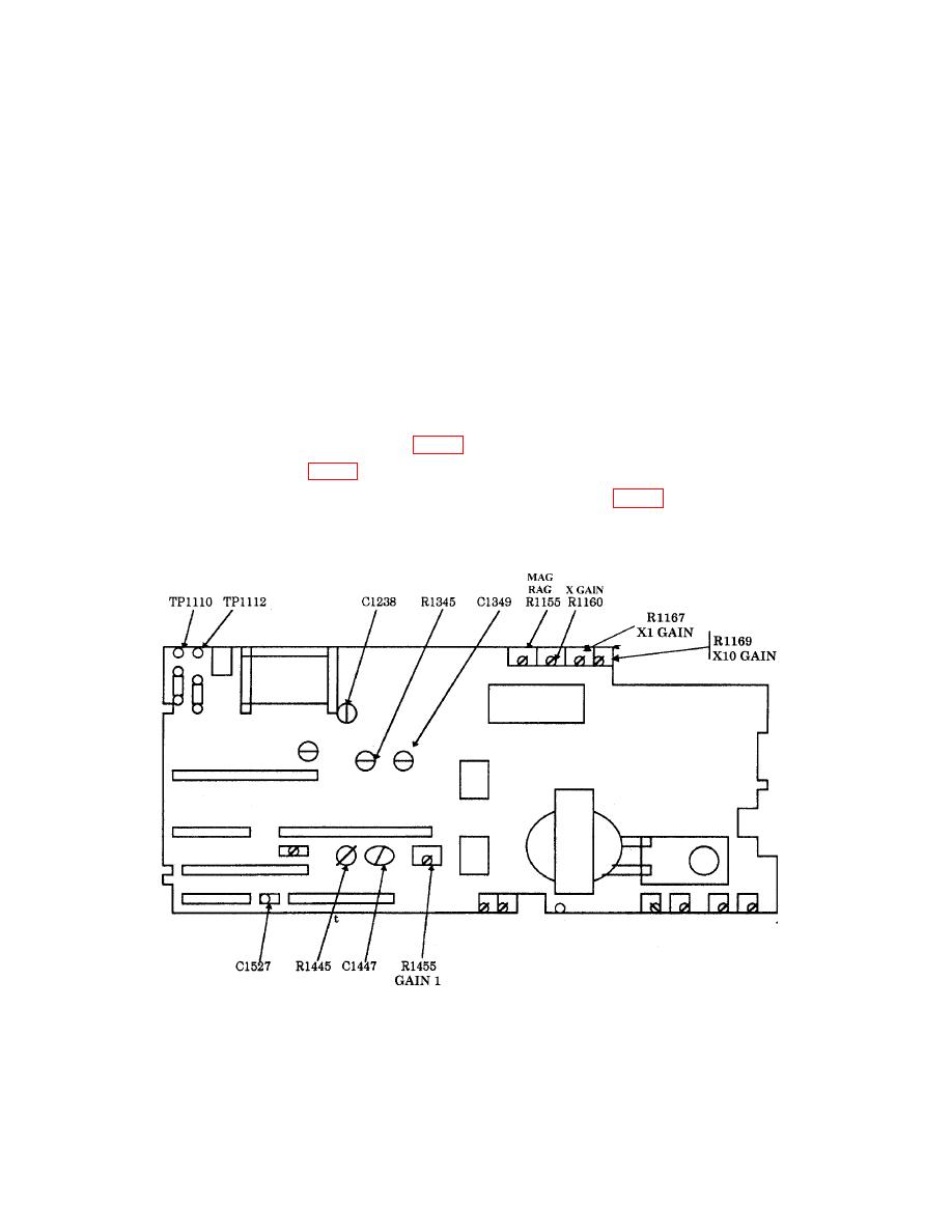
(2) Short TP1110 and TP1112 (fig. 6).
(3) Adjust R3466 (fig. 7) for a 0.6000 V dc indication on digital multimeter. (R).
(4) Disconnect short from between TP1110 and TP1112 (fig. 6).
(5) Disconnect digital multimeter from TI.
Figure 6. Main board.
19
