
TB 9-6625-2181-24
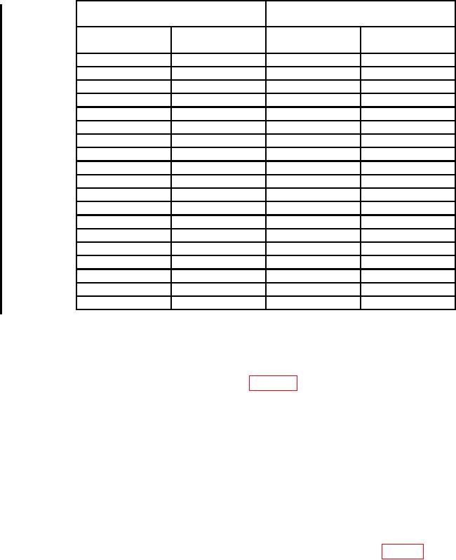
Table 5. Attenuator Accuracy
Digital voltmeter indications
Test instrument
(V dc)
0 to 10 DB
0 to 100 DB
switch settings
switch settings
Min
Max
2
0
35.23405 V
36.2629 V
3
0
31.40238 V
32.31934 V
4
0
27.98740 V
28.80464 V
5
0
24.94380 V
25.67217 V
6
0
22.23117 V
22.88034 V
7
0
19.81356 V
20.39213 V
8
0
17.65885 V
18.17450 V
9
0
15.73847 V
16.19804 V
10
0
14.0269 V
14.4365 V
0
10
13.8265 V
14.6458 V
0
20
4.37233 V
4.63140 V
0
30
1.38265 V
1.46458 V
0
40
437.233
mV
463.140
mV
0
50
138.265
mV
146.458
mV
0
60
43.72
mV
46.31
mV
0
70
13.83
mV
14.65
mV
0
80
4.372
mV
4.631
mV
0
90
1.343
mV
1.507
mV
V
V
0
100
425
477
13. Frequency Response
a. Performance Check
(1) Connect equipment as shown in figure 1.
(2) Set TI DB switches to 0.
(3) Adjust calibrator frequency to 1 kHz and amplitude to 10.0 mV.
Record
indication on true rms voltmeter.
(4) Set TI 0 to 10 dB switch to 10.
(5) Adjust calibrator output until true rms voltmeter indicates value recorded in (3)
above. Calibrator will indicate between 31.171 and 32.081 mV.
(6) Set 0 to 10 DB switch to 0 and 0 to 100 DB switch to 10.
(7) Adjust calibrator output until true rms voltmeter indicates value recorded in (3)
above. Calibrator will indicate between 30.726 and 32.546 mV.
(8) Repeat (6) and (7) above for attenuator settings listed in table 6 below; calibrator
will indicate within limits specified.
(9) Repeat technique of (2) through (8) above using frequencies of 100 Hz, 10 kHz,
and 100 kHz. Calibrator will indicate within limits specified.