
TB 9-6625-2197-40
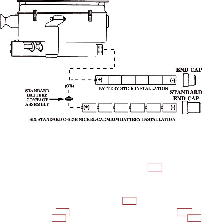
Figure 1. Battery Installation.
NOTE
A minimum of two fully charged battery sticks are required for
TI calibration.
d. Press and release TEST RPT (REPEAT) BUTTON S2 (fig. 2) pushbutton and
ensure that the display indication repeats.
e. Repeat technique of c above three times and ensure that the TI display will
sequence in the order ...2, 3, C, 1, 2, 3.
f. Press and release LAMP TEST BUTTON S3 (fig. 2) pushbutton to again obtain
indication in b above. While viewing the display, press and release the TEST RPT
must be displayed.
5