
TB 9-6625-2197-40
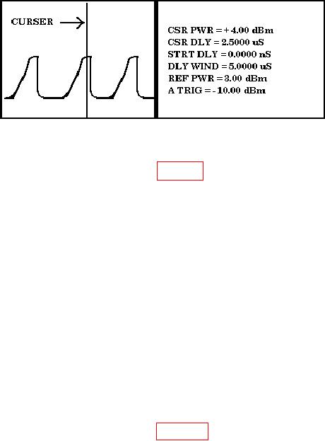
Figure 9. Example of Peak Power Meter Display.
(8) Connect equipment as shown in figure 8, CONNECTION B, except reverse SUM
and DIFF connections (50 Ω load to SUM and power sensor to DIFF).
NOTE
Only one pulse will be transmitted out of the DIFF connector
when TI LAMP TEST pushbutton is pressed. Set peak power
meter cursor delay to approximately 400 ns, delay window to
approximately 1.0000 s, and set reference power to
approximately -4 dBm.
(9) Press TI LAMP TEST pushbutton.
(10) Measure peak power from the DIFF connector. Peak power meter reading will
be between 0 and - 4 dBm.
b. Adjustments. No adjustments can be made.
10. Transmitter Frequency Accuracy
a. Performance Check
(1) Connect equipment as shown in figure 10.
(2) Set control box PWR switch to ON and set RPT and SEQ switches to OFF.
(3) Position frequency counter controls to measure pulsed RF.
(4) Press TI LAMP TEST pushbutton. Frequency counter will indicate between
1029.794 and 1030.206 MHz.
NOTE
Due to changing RF levels, repeat (4) above several times for
best results.