
TB 9-6625-2197-40
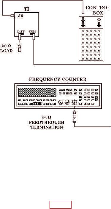
Figure 10. Transmitter Frequency Accuracy - Equipment Setup.
b. Adjustments. No adjustments can be made.
11. Receiver Sensitivity
NOTE
Insertion loss of circulator and cable between TI and radar test
set at 1090 MHz must be known before the following procedure
is performed.
a. Performance Check
(1) Connect equipment as shown in figure 11.
(2) Set radar test set GENERAL MENUS menus as listed in (a) through (d) below.
NOTE
All menu choices and selections not listed below are not
applicable and may be turned OFF. Make the following setup
selections then press FUNC 5 and store front panel menus in
any of the locations (1 through 4) for ease of operation. Front
panel menu retrieval is accomplished by pressing FUNC 6
then the location number.