
TB 9-6625-2211-24
(6) Set REPLIES MODULATION SEL switch to SIF.
NOTE
If an out-of-tolerance condition is noted during this
performance check refer to TM 11-6625-2610-40 to insure the
internal switches on A1 circuit board assembly are set
correctly.
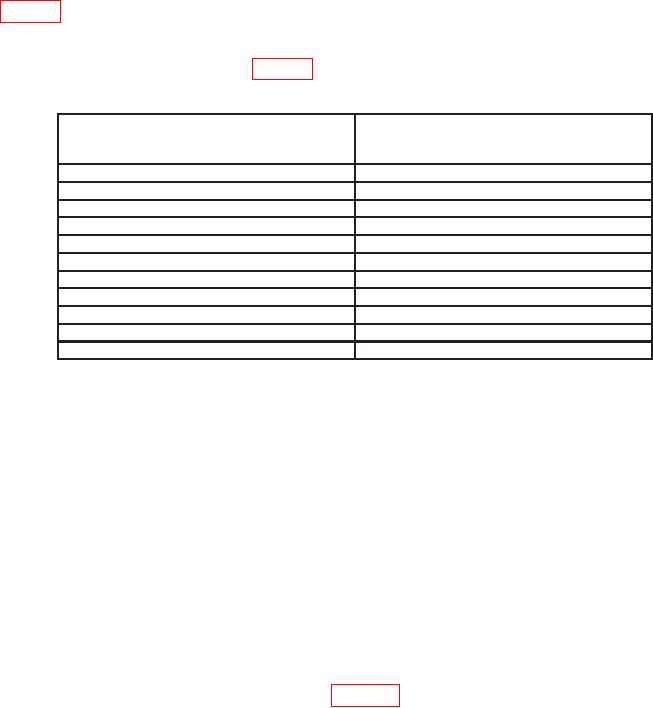
(7) Set REPLIES RANGE DELAY SEL (USEC) switches to first setting listed in
table 6. Frequency counter will indicate within limits specified.
(8) Repeat technique of (7) above for remaining REPLIES RANGE DELAY SEL
(USEC) switch settings listed in table 6. Frequency counter will indicate as specified.
Table 6. Range Delay
REPLIES RANGE DELAY SEL (USEC)
Frequency counter indications
switch settings
(Ps)
0111
544.0
r0.7
0222
655.0
r0.7
0333
766.0
r0.7
0444
877.0
r0.7
0555
988.0
r0.7
0666
1099.0
r1.1
0777
1210.0
r1.1
0888
1321.0
r1.1
0999
1432.0
r1.1
1999
2432.0
r1.1
2999
3432.0
r1.1
(9) Adjust oscilloscope controls as necessary to view TI reply pulse train.
(10) Set PRT SEL (USEC) (500 USEC MIN) switches to 3400. Reply pulse train
will disappear from oscilloscope display and TI REPLY INHIB indicator will light.
(11) Set PRT SEL (USEC) (500 USEC MIN) switches to 3600. After 10 seconds
REPLY INHIB indicator will extinguish and the pulses will be present on oscilloscope
display (oscilloscope time base may have to be changed to a slower sweep time in order to
observe reply pulse train).
b. Adjustments. No adjustments can be made.
13. SIF Reply and SUB Pulse Accuracy
a. Performance Check
(1) Connect equipment as shown in figure 4, connection A.
(2) Position controls as listed in 7 d above.