
TB 9-6625-2235-24
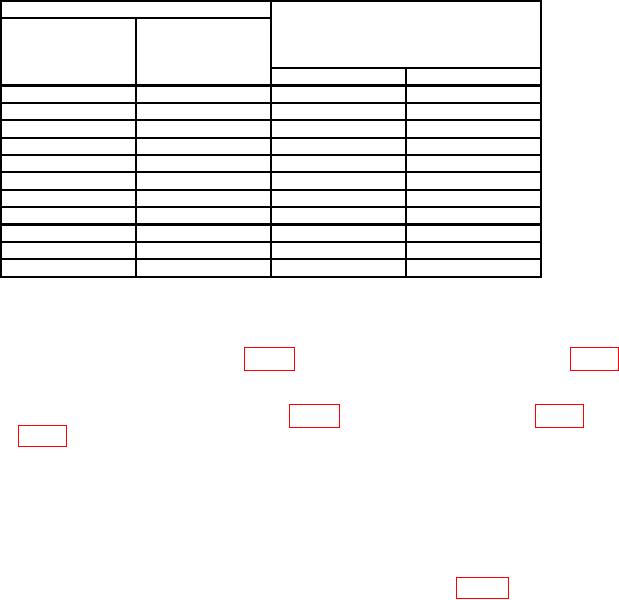
Table 5. Frequency Accuracy - Continued
Test instrument
FREQUENCY
FREQ SPAN/DIV
Synthesizer/level generator
MHz
switch
or signal generator frequency
readout
(MHz)
(MHz)
settings
Min
Max
1
100
200
kHz
98.96
101.04
140
200
kHz
138.96
141.04
180
200
kHz
178.96
181.04
200
1
MHz
194.8
205.2
400
1
MHz
394.8
405.2
600
1
MHz
594.8
605.2
800
1
MHz
794.8
805.2
1000
1
MHz
994.8
1005.2
1200
1
MHz
1194.8
1205.2
1400
1
MHz
1394.8
1405.2
1500
1
MHz
1494.8
1505.2
1Replace
synthesizer/level generator with signal generator.
b. Adjustments
for a multimeter indication between 14.48 and 14.52 V dc (R).
adjust A7R4 (fig. 9) for a multimeter indication between 5.99 and 6.01 V dc (R).
(3) Set FREQ SPAN/DIV switch to 5 MHz and RESOLUTION BW switch to 100 kHz.
(4) Turn FREQUENCY ZERO control fully ccw.
(5) Adjust TUNING control for FREQUENCY MHz readout of approximately -16.0.
feedthrough (within 1 division) on crt (R).
NOTE
Press FREQUENCY CAL pushbutton whenever TUNING
control is adjusted.
Disconnect comb generator, when
necessary, to center LO feedthrough.
(7) Position controls as listed in (a) through (d) below:
(a) FREQ SPAN/DIV switch in to couple position.
(b) RESOLUTION BW switch in to couple position.
(c) FREQ SPAN/DIV switch to 100 MHz/DIV.
17