
TB 9-6625-2235-24
(d) TUNING control to 500 MHz indication on FREQUENCY MHz readout.
(8) Connect comb generator to TI INPUT 50Ω.
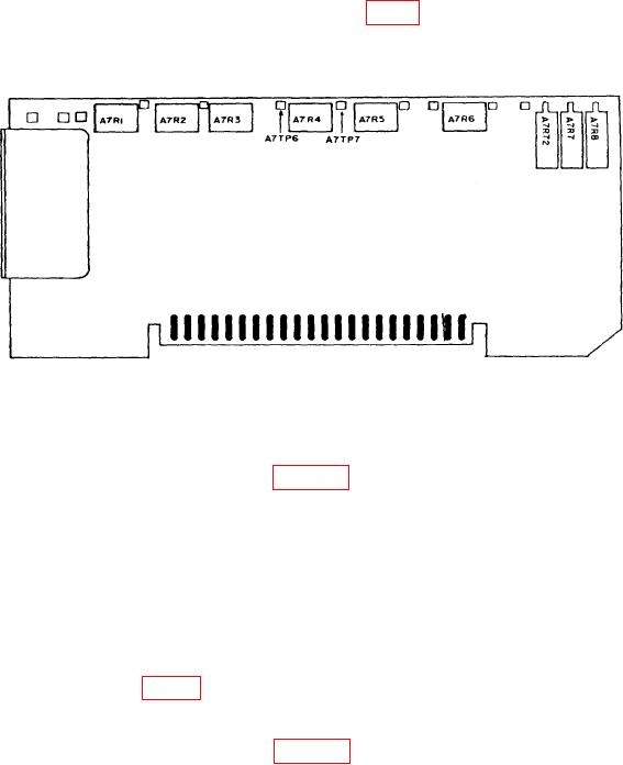
(9) Adjust TUNING control, A7R1 and A7R2 (fig. 9) to position a comb signal on lst
vertical graticule line and a second comb signal on 6th (center) vertical graticule line (R).
Figure 9. A7 frequency control - adjustment locations.
(10) Repeat (5) and (6) above.
(11) Connect equipment as shown in figure 7.
(12) Adjust synthesizer/level generator frequency to 1 MHz and RF output amplitude
to +10 dBm.
(13) Set FREQ SPAN/DIV switch to 1 MHz.
(14) Adjust TUNING control to approximately 11 MHz for view of one comb signal
per division and press FREQUENCY CAL pushbutton.
(15) Adjust A7R6 (fig. 9) to align comb signals (one per division) on vertical
graticule lines (R).
(16) Disconnect equipment shown in figure 7 and connect signal generator RF output
to TI INPUT 5OΩ.
NOTE
RF output level for signal generator will remain at -10 dBm for
frequencies of 190 and 200 MHz.
18