
TB 9-6625-2235-24
(d) REFERENCE LEVEL dBm switch to -50.
(e) Press LIN pushbutton in.
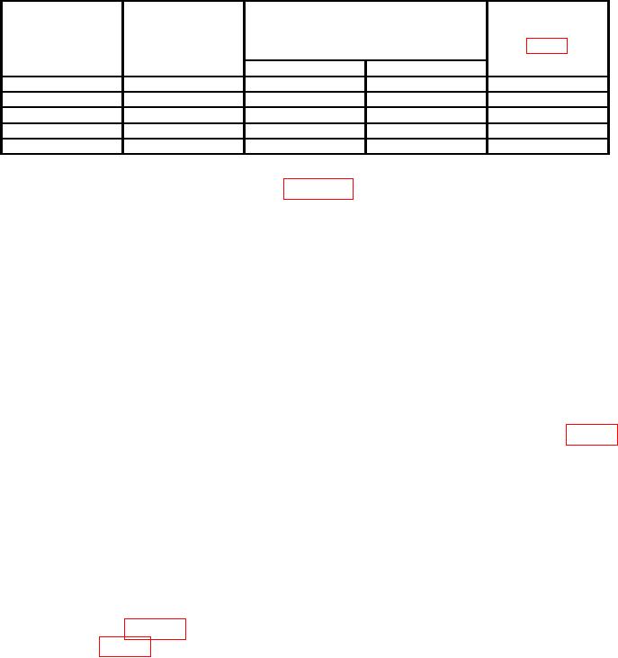
Table 10. Linear Gain Adjustments
Variable
Test instrument
Multimeter indications plus offset
REFERENCE
attenuator
voltage recorded in (7) above
Adjustments
LEVEL dBm
10 dB step
(MV)
switch settings
control setting
(dBm)
(dB)
Min
Max
-50
0
799
801
A14R34(R)
-60
10
795
805
A14R33(R)
-70
20
795
805
A14R30(R)
-80
30
795
805
A14R27(RO
-90
40
790
810
---
(29) Connect equipment as shown in figure 12.
(30) Set variable attenuator 10 dB step control to 0 dB.
(31) Adjust signal generator frequency controls to 301.4 MHz and RF output level
to -13 dBm.
(32) Set TEST/NORM switch (located on A12 board) to TEST position.
display on crt. (Reduce signal generator RF output, if necessary.)
(34) Adjust signal generator RF output controls for a multimeter indication of 700 mV.
(35) Set REFERENCE LEVEL switch to -80 dBm.
(36) Set variable attenuator 10 dB step control to 30 dB and adjust A14R3 (fig. 14)
for a multimeter indication of 700 mV (R).
(37) Repeat (34) through (36) above until multimeter indication is between 698 and
702 mV.
(38) Set REFERENCE LEVEL switch to -50 dBm.
(39) Set variable attenuator 10 dB step control to 0 dB.
(40) Set REFERENCE LEVEL switch and variable attenuator 10 dB step control to
settings as listed in table 11. If any deviation from reference is not within specified limits,
readjust A14R3 (fig. 14) for best (in limits) compromise (R).
34