
TB 9-6625-2235-24
NOTE
See examples 1 and 2 in b (8) above.
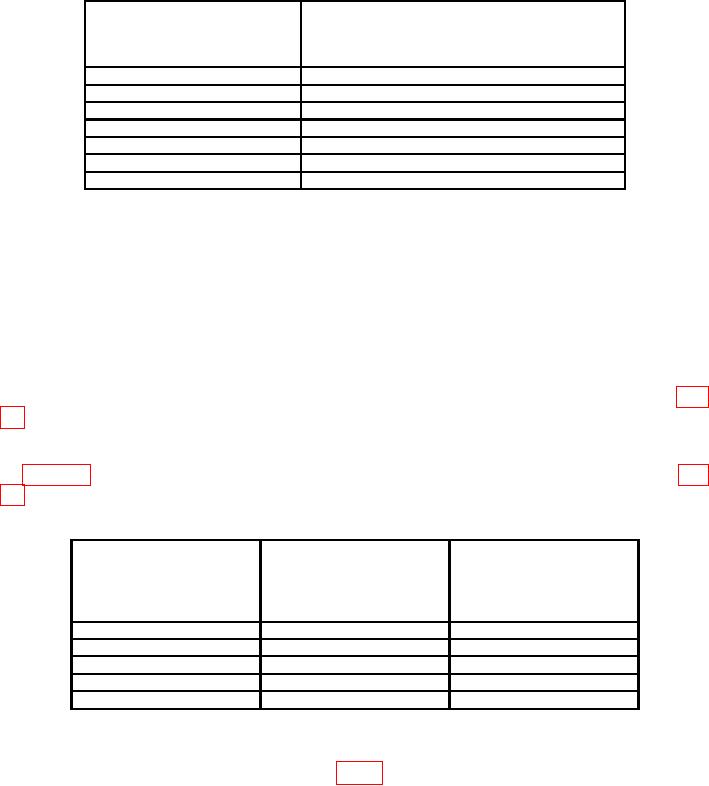
Table 12. Log Fidelity
Variable attenuator
10 dB step
indications
control settings
corrected for offset
(dB)
(MV)
0
800 + offset l m V
10
700 + offset 3 mv
20
600 + off set 4 mV
30
500 + offset 4 mV
40
400 + offset 5 mV
50
300 + offset 4 mV
60
200 + offset 7 mV
(46) Set REFERENCE LEVEL switch to -50.
(47) Press 1 dB/DIV pushbutton in and set variable attenuator 10 dB step control to 0 dB.
(48) Adjust signal generator RF output controls for a multimeter indication of 700
mV (do not include offset value).
(49) Set REFERENCE LEVEL switch to -90.
(50) Set variable step attenuator 10 dB step control to 40 dB and adjust A14R1 (fig.
14) for a multimeter indication of 700 mV (do not add offset value) (R).
(51) Set REFERENCE LEVEL switch and variable attenuator to settings as listed
13) for best (in limits) compromise (R).
Table 13. Log Gain
Test instrument
Variable attenuator
REFERENCE LEVEL
10 dB step
Deviation from crt
dBm
reference1
control settings
switch settings
(dB)
(dBm)
-50
0
0.3 div
-60
10
0.3 div
-70
20
0.3 div
-80
30
0.3 div
-90
40
0.3 div
1Variable
attenuator errors must be added algebraically.
(52) Return TEST/NORM switch (located on A12 board) to NORM. Remove test
cable and reconnect W7 (red) cable to A9J1 (fig. 1).
36