
TB 9-6625-2235-24
r. Press 10 dB/DIV pushbutton in and set REFERENCE LEVEL switch to -20 dBm.
s. Connect 280 MHz CAL OUTPUT to TI INPUT 50Ω.
t. Center signal on crt with TUNING control and press FREQUENCY CAL
pushbutton three times. FREQUENCY MHz readout will indicate between 275 and 285
MHz.
u. Press LIN pushbutton in.
v. Position signal peak at top crt graticule line with REF LEVEL FINE control.
w. Press 10 dB/DIV pushbutton in and adjust VERTICAL GAIN control to position
signal peak at top crt graticule line.
x. Repeat (u) through (w) above until signal peak remains at top crt graticule line when
amplitude scale is changed from 10 dB/ DIV to LIN and back to 10dB/DIV.
y. Set REF LEVEL FINE control to 0, and REFERENCE LEVEL switch to -30
dBm.
z. Press LIN pushbutton in and position signal peak at top crt graticule line with REF
LEVEL CAL control.
NOTE
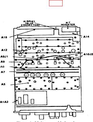
Refer to major assembly location (fig. 1) for board location.
Figure 1. Major assembly locations.
7