
TB 9-6625-2235-24
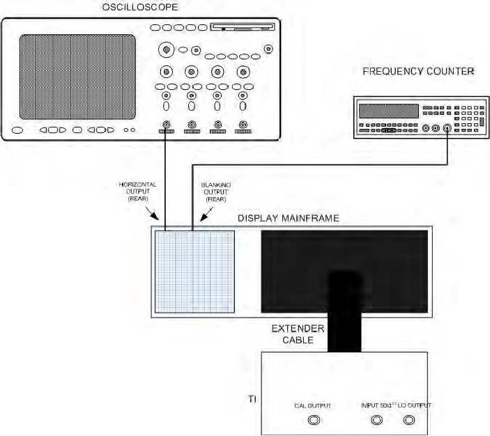
Figure 4. Sweep time - equipment setup.
(2) Set SWEEP TIME/DIV switch to 1 ms and SWEEP TRIGGER switch to
FREE RUN.
(3) Measure ramp and dead time with oscilloscope.
Ramp voltage will be
approximately -5 to +5 V and dead time will be between 0.25 and 0.40 ms. Record actual
dead time value.
(4) Set SWEEP TIME/DIV switch to 5 ms (2 ms for SN prefixed 2215A and below).
Measure and record dead time of ramp. Dead time of ramp will be between 6 and 9 ms.
(5) Set SWEEP TIME/DIV switch to 1 ms. If frequency counter does not indicate
10 ms + dead time of ramp [(3) above] 0.8 Ms, perform b (1) below.
11