
TB 9-6625-2237-24
11. Amplitude and Frequency Outputs
a. Performance Check
NOTE
To gain access to the RF oscillator in RF module assembly,
remove six screws and lift panel assembly away from case.
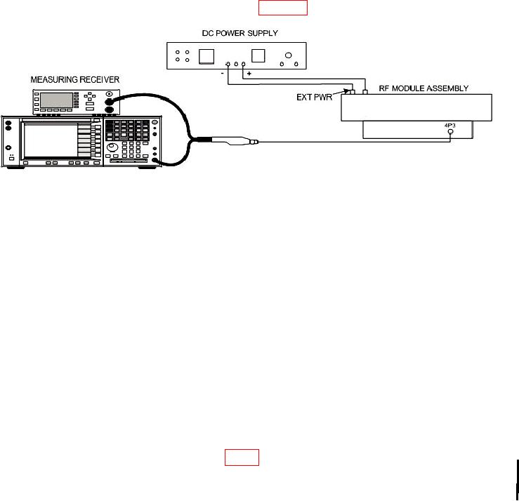
(1) Connect dc power supply as shown in figure 5.
Figure 5. Receiver frequency - equipment setup.
NOTE
Monitor dc power supply with multimeter (dc mode).
(2) Adjust dc power supply controls for a multimeter indication between 12.5 and
13.5 V dc.
(3) Perform (4) below to install the calibration antenna No. 1 (243.0 MHz).
(4) Perform (a) through (e) to install calibration antennas:
(a) Unlatch and open test chamber assembly.
(b) Install calibration antenna on the antenna plate assembly.
(c) Set load carriage assembly to value recorded in 9 a (13) above.
(d) Attach antenna plate assembly to the key slots on the end of the test
chamber and place antenna between load carriage contacts.
(e) Close test chamber cover and latch.
(5) Set RADIO SELECT switch to PRC-90 (243.0).
(6) Set REC TEST/XMIT TEST switch to REC TEST position.
(7) Disconnect RF cable from 4P3 (fig. 5).
(8) Set measuring receiver for automatic operation to measure RF frequency.
CHANGE 1 11