
TB 9-6625-2237-24
output indication value recorded in table 4 for test setting of 19.6 dBm.
(19) Press and hold RF POWER PRESS button. The green PASS indicator will be
illuminated and the red FAIL indicator will be off; if not, repeat (6) through (17) above.
output indication value recorded in table 4 for test setting of 18.6 dBm.
(21) Press and hold R.F. POWER PRESS button. The red FAIL indicator will be
illuminated and the green PASS indicator will be off; if not, repeat (6) through (17) above.
(22) Press signal generator RIF OFF/ ON key to OFF position.
(23) Repeat technique of (2) above to install calibration antenna NO. 2 (282.8 MHz).
(24) Set RADIO SELECT switch to PRC-90 (282.8).
(25) Repeat (6) through (22) for 282.8 MHz frequency setting.
(26) D o n o t d i s c o n n e c t e q u i p m e n t s e t u p . E q u i p m e n t s e t u p w i l l b e u s e d i n
n e x t paragraph.
b. Adjustments
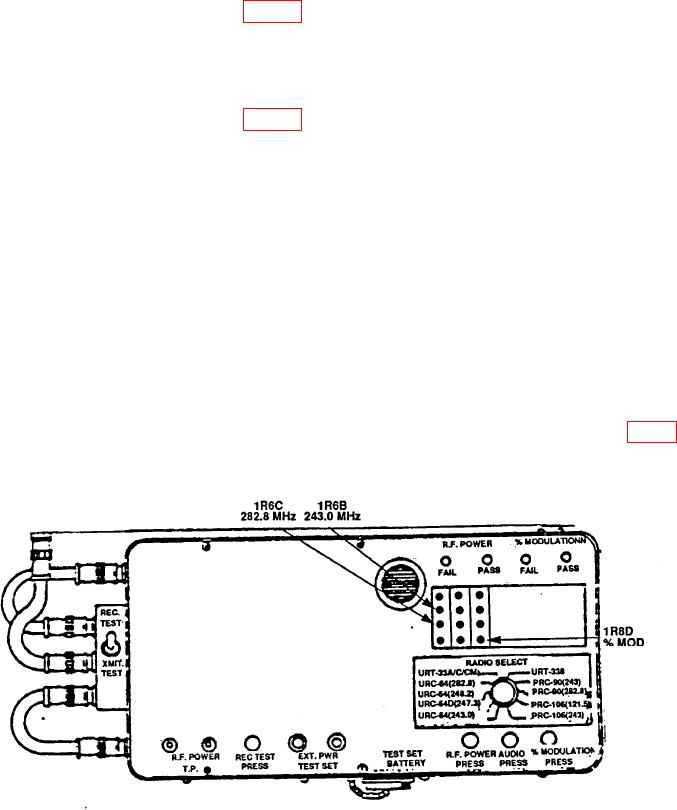
(1) Press and hold RF POWER PRESS button and adjust 1R6B 243.0 MHz (fig. 4)
until both PASS and FAIL indicators blink randomly.
Figure 4. RF power and modulation percentage threshold adjustment.