
TB 9-6625-2240-24
(11) Move TI connection from CH1 to CH2.
(12) Press VERT MODE CH2 pushbutton and set CH2 AC-GND-DC switch to DC.
(13) Set CH2 VOLTS/DIV switch to 2 m (5 m for Tektronix, Type 475A).
(14) Press oscilloscope calibrator VOLTAGE pushbutton to illuminate green LED
and ensure frequency is set to 1 kHz.
(15) Perform steps (a) through (c) below:
(a) Use technique of (b) and (c) below for TI VOLTS/DIV switch settings and
oscilloscope calibrator VOLTAGE outputs of those listed in table 4.
(b) Rotate TI CH 2 POSITION knob to center trace on crt.
(c) Rotate oscilloscope calibrator knob located below EDIT FIELD pushbutton
to obtain 6 divisions of vertical display. Oscilloscope calibrator err display will indicate
within limits specified in table 4.
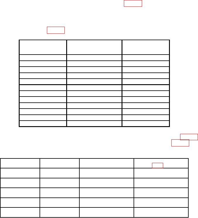
Table 4. Channel 2 Vertical Deflection Accuracy
Test instrument
Oscilloscope calibrator
Oscilloscope calibrator
VOLTS/DIV
Err display limits
Voltage output
( %)
switch settings
3
2
m
12
mV
3
51
m
30
mV
3
10
m
60
mV
3
20
m
120
mV
3
50
m
.3
V
3
.1
V
.6
V
3
.2
V
1.2
V
3
.5
V
3.0
V
3
1
V
6.0
V
3
2
V
12.0
V
3
5
V
30.0
V
3
V1
10
60.0
V
1For
Tektronix, Type 475A.
b. Adjustments. Set oscilloscope calibrator to required parameter listed in table 5
for particular TI you are calibrating. Perform appropriate adjustments listed in table 5 for
6 divisions of vertical display on TI.
Table 5. Adjustment Guide
Parameter
Tektronix
Adjustments
Serial number
(mV gain)
type
(fig. 1) (R)
2
475
Below B250000
CH 1 R125
CH 2 R225
2
475
B250000 and up
CH 1 R195
CH 2 R295
5
475
All SN's
CH 1 R165
CH 2 R265
5
475A
---
CH 1 R195
CH 2 R295
10
475A
---
CH 1 R165
CH 2 R265
7