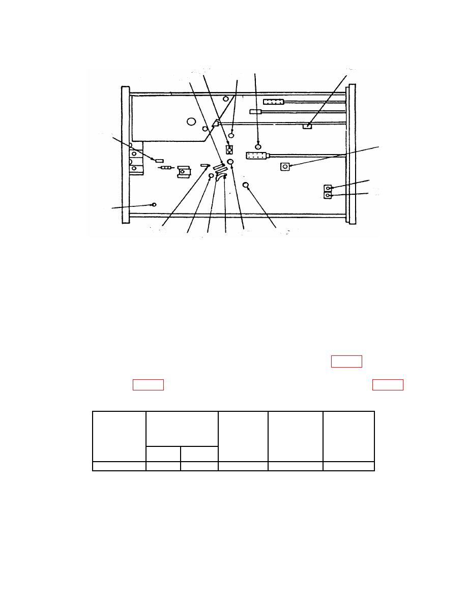
TB 9-6625-2240-35
R1515
R1155
C1179
C1253
+15 V
R1430
+50 V
R950
R936
R938
-15 V
+ 50 V
C1009
C1233
+110 V +5 V
-8 V
TP
(6) Perform steps (a) through (d) below:
(a)
Set TI A COUPLING switch to LF REJ.
(b)
Set TI A SOURCE switch to CH1.
(c)
Press TI X10 MAG pushbutton to on (in).
(d)
Press TRIG MODE NORM pushbutton to (in).
NOTE
You may need to adjust A TRIGGER SLOPE LEVEL for a
stable display in step (8) below.
(7) Set oscilloscope calibrator output and TI to settings listed in table 7.
(8) Adjust horizontal POSITION control to align 1 marker per division. TI will
required.
Test
instrument
Test
Test instrument
TIME/DIV
indications
instrument
VOLTS/DIV
switch settings
Test
1 per division
calibrator
MARKER
switch
instrument
minor
A
B
output
settings
adjustments
divisions
.5 V
5 ns
2
b(2)
.05 s
.05 s
(9) Set A SOURCE switch to NORM, and A COUPLING switch to AC.
(10) Press X10 MAG (IN) pushbutton to off (out).
10


