
TB 9-6625-2240-35
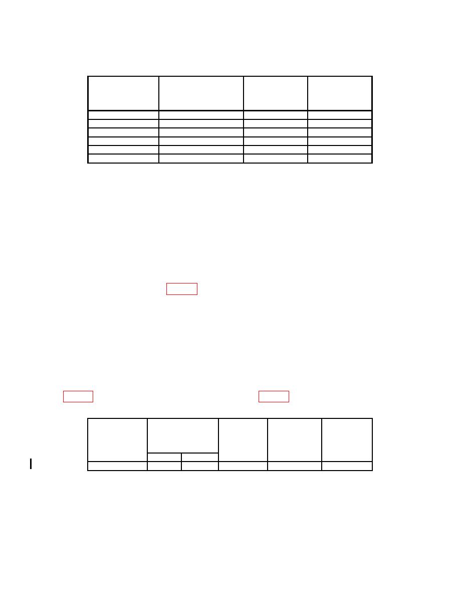
Table 8. Sweep Timing Accuracy - Continued
Oscilloscope
calibrator err
Oscilloscope calibrator
Test instrument
MARKER
TIME/DIV
display limits
Test instrument
output settings
switch settings
adjustments
( %)
10
ms
10
ms
2
20
ms
20
ms
2
50
ms
50
ms
2
.1
s
.1
s
2
.2
s
.2
s
2
.5
s
.5
s
2
a. Performance Check
(1) Position controls as listed in (a) through (g) below:
(a) HORIZ DISPLAY A INTEN pushbutton pressed (in).
(b) DELAY TIME POSITION dial to 1.00.
(c) Press TRIG MODE AUTO pushbutton to (in).
(d) Press X10 MAG (IN) pushbutton to (in).
(e) Ensure oscilloscope calibrator CHAN 1 is connected to TI CH1 through 50Ω
feedthrough termination.
(f) Set TI VOLTS/DIV, TIME/DIV switch settings and oscilloscope calibrator
(g) Adjust A TRIGGER SLOPE LEVEL as needed for a stable trace on crt.
NOTE
For Tektronix, Type 475, SN B250000, and above, and
Tektronix, Type 475A, perform (3) below then proceed to (4).
For all other models, proceed to (4) below.
(2) Adjust horizontal POSITION control to align 1st time marker with 1st graticule
line. Rotate oscilloscope calibrator knob located below EDIT FIELD output to obtain 1
marker per division on TI. Oscilloscope calibrator err display will be within limits specified
Oscilloscope
Oscilloscope
Test instrument
TIME/DIV
Test
calibrator err
calibrator
Test instrument
MARKER
VOLTS/DIV
switch settings
instrument
display limits
output
switch settings
adjustments
(%)
A
B
.5
2
b(1)
10 s
1 s
1 s
12 CHANGE 1
