
TB 9-6625-2250-24
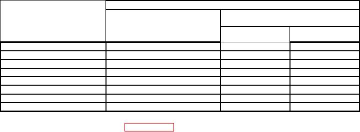
Table 9. Linear IF Gain Uncertainty
Synthesizer/level
Test instrument
MKR indications
generator amplitude
AMPLITUDE (REF LVL)
settings
settings
(dB)
(dBm)
Min
Max
(dBm)
0
-10
-11
-9
-10
-20
-21
-19
-20
-30
-31
-29
-30
-40
-41
-39
-40
-50
-51
-49
-50
-60
-61
-59
-60
-70
-71
-69
-70
-80
-81
-79
b. Adjustments. Refer to paragraph 1 a.
13. Residual FM
a. Performance Check
(1) Connect synthesized signal generator RF Output to TI INPUT 50 .
(3) Press TI keys and enter values using DATA keys listed in (a) through (v) below:
INSTRUMENT STATE PRESET.
(a)
FREQUENCY then [CENTER FREQ] to 2.5 GHz.
(b)
SPAN then [SPAN WIDTH] to 1 MHz.
(c)
AMPLITUDE then [REF LEVEL] to -10 dBm.
(d)
[LOG dB/DIV] to 1 dB.
(e)
CONTROL BW then [RES BW] to 3 kHz.
(f)
MARKER PEAK SEARCH.
(g)
[SIG TRK ON].
(h)
SPAN then [SPAN WIDTH] to 10 kHz.
(i)
CONTROL BW then [RES BW] to 1 kHz.
(j)
MARKER ON.
(k)
[SIG TRK OFF].
(l)
MARKER PEAK SEARCH.
(m)
MARKER MKR .
(n)
[MARKER CF].
(o)
[MARKER REF LVL].
(p)
MARKER OFF.
(q)
CONTROL TRIG.
(r)
[SINGLE].
(s)
22