TB 9-6625-2263-35
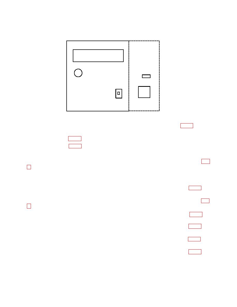
DIGITAL PBC
ASSEMBLY
DIGITAL CONTROLLER BOARD
S1
(7) Set calibrator for a 1.9 V output. Adjust DC BUFFER R251 1V (fig. 1) for TI
indication between 1.89999 4 and 1.90000 6 VD (R).
(8) Press S1 (fig. 2) to return to normal mode.
(9) Press S1 (fig. 2) to select cal digit mode.
(10) Set calibrator to STANDBY and disconnect calibrator from TI.
(11) Short TI V/Ω INPUT HI and LO. Adjust A/D ANALOG R513 A/D ZERO (fig.
(12) Remove short and connect calibrator OUTPUT HI and LO to TI V/Ω INPUT
HI and LO.
(13) Set calibrator for a -8.1 V output. Adjust A/D ANALOG R522 8 BIT (fig. 1) for
TI indication between -8.0999 8 and -8.1000 2 VD (R).
(14) Set calibrator for a +8.1 V output. Adjust A/D ANALOG R504 NEG REF (fig.
(15) Set calibrator for a 4.1 V output. Adjust A/D ANALOG R521 4 BIT (fig. 1) for
TI indication between 4.0999 8 and 4.1000 2 VD (R).
(16) Set calibrator for a 2.1 V output. Adjust A/D ANALOG R520 2 BIT (fig. 1) for
TI indication between 2.0999 8 and 2.1000 2 VD (R).
(17) Set calibrator for a 1.1 V output. Adjust A/D ANALOG R519 1 BIT (fig. 1) for
TI indication between 1.0999 8 and 1.1000 2 VD (R).
(18) Set calibrator for a .6 V output. Adjust A/D ANALOG R518 1/2 BIT (fig. 1) for
TI indication between .5999 8 and .6000 2 VD (R).
8


