
TB 9-6625-2274-40
(5) Adjust digitizing oscilloscope offset until the flattest portion of waveform is
centered on horizontal center graticule.
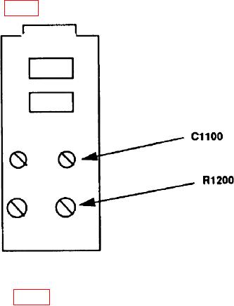
(6) Adjust R1200 (fig. 3) for a maximum flatness on the top pulse (R).
Figure 3. Pulse head fast edge leading aberration adjustment locations.
(7) Adjust C1100 (fig. 3) to equalize the aberrations on each side of horizontal
graticule center line (R).
(8) Repeat (6) and (7) above as necessary until optimum displayed pulse is obtained.
(9) Digitizing oscilloscope will display a pulse indicating aberrations <3 percent of
pulse amplitude. Adjacent pulse peaks will not exceed 4 percent peak-to-peak.
(10) Press OUTPUT ON pushbutton off and remove all connections from TI.
(11) Repeat paragraphs 25 through 27 above.
28. Fast Edge Pulse Frequency
a. Performance Check
s/D.
(1) Acquire signal using digitizing oscilloscope and set sweep speed to 1
Digitizing oscilloscope will display a waveform cycle.
pushbutton to highlight 1 kHz.
(2) Press AMPLITUDE MODE FREQ
s /D.
(3) Acquire signal using digitizing oscilloscope and set sweep speed to 100
Digitizing oscilloscope will display a waveform cycle.
pushbutton to highlight 100 Hz and set
(4) Press AMPLITUDE MODE FREQ
digitizing oscilloscope timebase to 1 ms/D.
(5) Acquire signal using digitizing oscilloscope and set sweep speed to 1 ms/D.
Digitizing oscilloscope will display a waveform cycle.