
TB 9-6625-2280-40
(12) Press any UNITS key (nS or S or mS key.) Wait for TI to calibrate itself
before proceeding to (13) below.
(13) Disconnect RF detector B from CALIBRATOR 1 GHZ output.
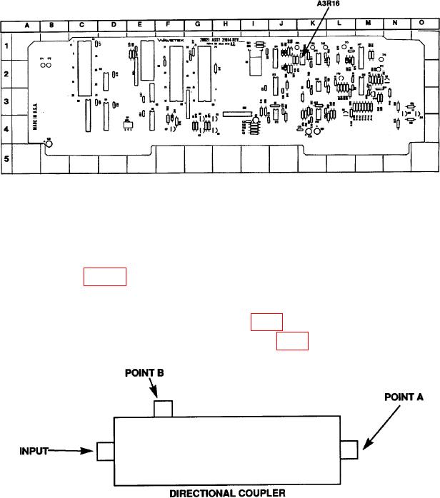
Figure 1. A3R16 - Adjustment Location.
10. Power Linearity Test
a. Performance Check
(1) Refer to figure 2 and connect equipment as listed in (a) through (c) below:
(a) Connect signal generator RF OUTPUT to directional coupler INPUT.
(b) Connect power meter to POINT A (fig. 2) of directional coupler.
(c) Connect 50 Ω termination to POINT B (fig. 2) of directional coupler.
Figure 2. Power Linearity - Equipment Setup.