
TB 9-6625-2283-24
(40) Adjust MARKER control until marker on crt is on the shoulder of the third step
(best position obtainable). Record LCD reading. Set POWER switch to OFF. If any TI
indications are not within 5 meters of multimode test fiber certificate value, perform b below.
b. Adjustments
(1) Set POWER switch to OFF and remove the cover over the deflection
amplifier module.
(2) Perform (a) through (c) below:
(a) Remove the narrow section and one wide section of the extender board set.
(b) Pull up the deflection amplifier board.
(c) Insert the extender sections to interface the board to the TI.
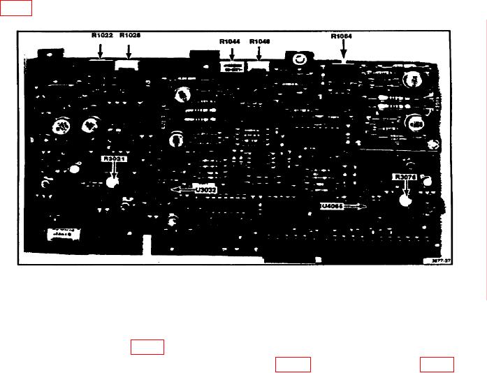
(3) Set multimeter range to +200 mV dc and connect the probe to pin 2 of U3032
(fig. 2) (R).
Figure 2. Deflection amplifier.
(4) Set POWER switch to ON.
(5) Adjust R3021 (fig. 2) for a multimeter indication of 0 V (R).
multimeter indication of 0 V (R).
(7) Perform (a) through (c) below:
(a) Set POWER switch to OFF.
(b) Adjust DIST/DIV control to 5.
POSITION control fully cw.
(c) Adjust
7