
TB 9-6625-2293-24
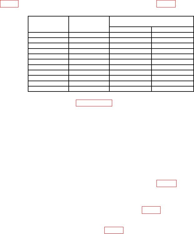
(33) Repeat technique of (28) and (30) through (32) above for settings listed in
Table 5. Delta Volts with Cursors
Test instrument
Test instrument ΔV readout indications
VOLTS/DIV
calibrator
output settings
switch settings
Min
Max
2m
V
10
mV
9.81 mV
10.20 mV
5
mV
20
mV
19.6 mV
20.4 mV
10
mV
50
mV
49.0 mV
50.9 mV
20
mV
0.1
V
98.1 mV
102.0 mV
50
mV
0.2
V
196 mV
204
mV
100
mV
0.5
V
490 mV
509
mV
200
mV
1.0
V
0.981 V
1.02 V
500
mV
2.0
V
1.96 V
2.04 V
1.0
V
5.0
V
4.90 V
5.09 V
2.0
V
10.0
V
9.81 V
10.2
V
5.0
V
20.0
V
19.6
V
20.4
V
b. Adjustments. Perform SECTION IV below.
10. Triggering
a. Performance Check
(1) Press ΔV pushbutton to off (cursors off).
(2) Push TRIGGER MODE switch down to NORM.
(3) Set oscilloscope calibrator for a CHAN 1, VOLTAGE mode output of 10 mV at 1
kHz frequency.
(4) Set CH 1 VOLTS/DIV switch to 2 mV.
(5) Adjust TRIGGER LEVEL control for most positive voltage that produces a
barely triggered display for both + and - SLOPE. If A TRIGGER LEVEL readout
indication is not within limits specified in + peak column of table 6 for 2 mV setting,
perform b below.
(6) Adjust TRIGGER LEVEL control for most negative voltage that produces a
barely triggered display for both + and - SLOPE. If A TRIGGER LEVEL readout
indication is not within limits specified in - peak column of table 6 for 2 mV setting, perform
b below.
(7) Repeat technique of (5) and (6) above for remaining VOLTS/DIV switch settings
and oscilloscope calibrator outputs listed in table 6.