
TB 9-6625-2294-35
Oscilloscope
calibrator
Test
err display
instrument
Oscilloscope
Test instrument
VOLTS/DIV
limits
display
calibrator
VOLTAGE
switch settings
(%)
amplitude
output settings
(mV)
divisions
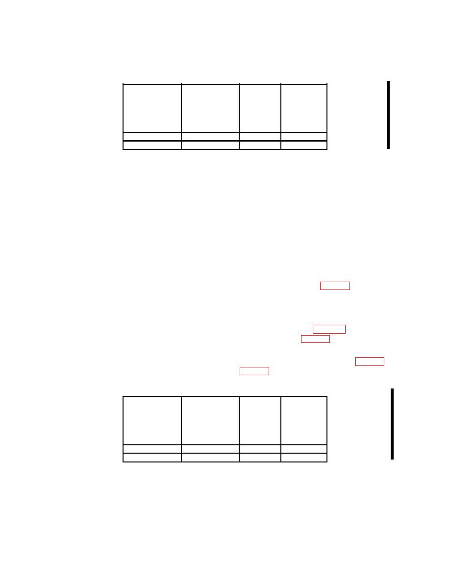
100
.5 V
5
10
500
2.0 V
4
10
NOTE
Press oscilloscope calibrator CHANNEL pushbutton. Next
press blue soft pushbutton located below CHAN 4 on
oscilloscope calibrator when SELECT CHANNEL is displayed.
(29) Perform steps (a) and (b) below:
(a) Set TI TRIGGER SOURCE CH 3 off and CH 4 to on.
(b) VERTICAL MODE CH 3 off and CH 4 on.
(30) Perform steps (a) and (e) below:
(a) Set oscilloscope calibrator output frequency to 1 kHz.
(b) Set oscilloscope calibrator SOURCE Z to 1 MΩ.
(c) Set oscilloscope calibrator output as listed in first row of table 8.
(d) Set TI VOLTS/DIV switch for .1 V on TI crt display.
(e) Adjust TI CH 4 POSITION control as necessary to view signal trace.
(31) Rotate knob located below EDIT FIELD pushbutton on oscilloscope calibrator to
obtain TI display amplitude divisions as listed in first row of table 8. Oscilloscope
calibrator err display will be within limits as listed in first row of table 8; if not, perform b
below.
(32) Repeat technique of step of (30) and (31) above for remaining row of table 8. TI
waveform will be within amplitude limits listed in table 8; if not, perform b below.
Oscilloscope
calibrator
Test
err display
instrument
Oscilloscope
Test instrument
VOLTS/DIV
limits
display
calibrator
VOLTAGE
switch settings
(%)
amplitude
output settings
(mV)
divisions
100
.5 V
5
10
500
2.0 V
4
10
