
TB 9-6625-2296-24
(18) If measuring receiver indication, minus residual FM recorded in (5) above, is not
within limits specified in table 20 for appropriate TI setting, perform b below.
(19) Repeat (14) through (18) for remaining settings listed in table 20.
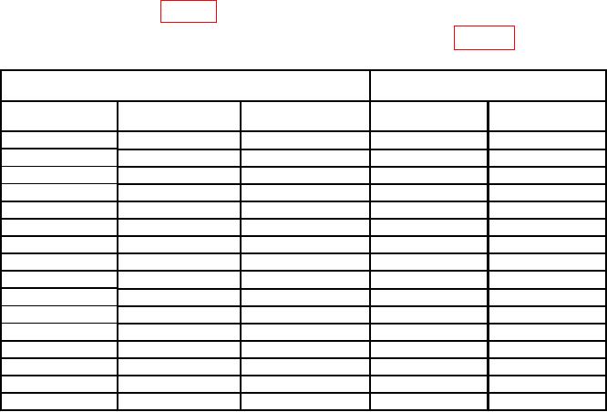
Table 20. Frequency Modulation Accuracy.
Measuring receiver1
Test instrument
indications
RF
Modulation
Deviation
rate
modulation
Min
Max
750 kHz
30
Hz
100
Hz
0.090
0.110
750 kHz
30
Hz
10 kHz
9.50
10.50
750 kHz
30
Hz
25 kHz
22.50
27.50
750 kHz
1 kHz
100
Hz
0.090
0.110
750 kHz
1 kHz
10 kHz
9.50
10.50
750 kHz
1 kHz
25 kHz
22.50
27.50
750 kHz
10 kHz
10 kHz
9.50
10.50
750 kHz
10 kHz
25 kHz
22.50
27.50
900 MHz
30
Hz
100
Hz
0.090
0.110
900 MHz
30
Hz
10 kHz
9.50
10.50
900 MHz
30
Hz
25 kHz
22.50
27.50
900 MHz
1 kHz
100
Hz
0.090
0.110
900 MHz
1 kHz
10 kHz
9.50
10.50
900 MHz
1 kHz
25 kHz
22.50
27.50
900 MHz
20 kHz
10 kHz
9.50
10.50
900 MHz
20 kHz
25 kHz
22.50
27.50
1 Set
measuring receiver filters as needed.
b. Adjustments
(1) Press key sequence listed in (a) through (f) below:
(a) MODE MTRS ..........................
Meters Menu
(b) AUX (F6) ..................................
Auxiliary
(c) MEMORY RCL .......................
Recall
(d) FIELD SELECT ..................
Highlight 10. Factory Defaults
(e) DATA ENTRY ENTER ..........
Factory Defaults recall
NOTE
Assure highlighted area indicates YES before proceeding.
(f) DATA ENTRY ENTER ..........
Factory Defaults restored
(2) Connect measuring receiver power sensor module to TI T/R.
(3) Set measuring receiver to measure FM deviation, with low pass filter of 15 kHz,
high pass filter of 300 Hz, and PEAK/2 detector selected.
(4) Press key sequence listed in (a) through (k) below
59