TB 9-6625-2296-35
(15) Connect SMB-to-SMB extender coax in place of cable 23 on A4 module (fig. 1).
and press POWER key (ON illuminated).
(16) Set signal generator for a 10.7 MHz, -30 dB output.
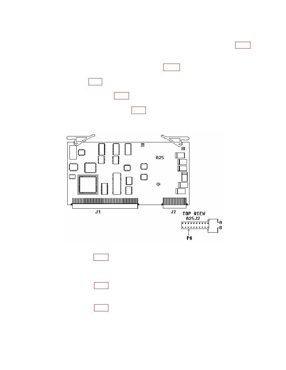
(17) Connect multimeter to A25 J2 pin 8B (fig. 4) on digitizer module and set
multimeter to measure volts dc.
(18) Adjust A4R5 (fig. 1) on Log-IF board until multimeter indicates 1.4 V dc 20 mV dc (R).
(19) Press Norm (F1) (Normalize) key, allow normalize cycle to complete, and
reconnect cable 23 on A4 module (fig. 1) to its original position.
(20) Set signal generator for a 121.5 MHz, -40 dB output and verify signal peak is
within 1 dB of -40 dBm; readjust A4R5 (fig. 1) as necessary.
(21) Press Scan (F3) (Scan Width) and DATA SCROLL arrow keys to select 50 kHz
scan width.
(22) Adjust A4R5 (fig. 1) to position signal on -40 dBm line (1st major division from
the top) (R).
(23) Press DATA SCROLL arrow key to select 1 kHz scan width and press DATA
ENTRY ENTER key.
(24) Adjust A4R96 (fig. 1) for a -40 dBm display on TI (R).
(25) Press DATA SCROLL arrow key to select 10 kHz scan width and press DATA
ENTRY ENTER key.
(26) Adjust A4R57 (fig. 1) for a -40 dBm display on TI (R).
(27) Press DATA SCROLL arrow key to select 1 MHz scan width and press DATA
ENTRY ENTER key.


