
TB 9-6625-2297-35
(4) Press FUNCTION SHIFT key then DATA ENTRY PWR REF/⇒ key.
If
frequency counter does not indicate between 49.5 and 50.5 MHz, perform b below.
(5) Disconnect frequency counter from TI.
b. Adjustments
(1) Adjust L5 (fig. 1) for a frequency counter indication between 49.5 and 50.5 MHz
(R).
a. Performance Check
(1) Press DATA ENTRY PRESET/LOCAL key then DATA ENTRY ENTER key.
(2) Set multimeter to measure resistance.
NOTE
Power meter is a standard used to calibrate the TI.
Instructions in this text which refer to power meter setup or
connections refer to the standard power meter.
(3) Set power meter LINE switch to OFF position.
(4) Connect multimeter between center conductor of power meter rear panel VRF
connector and pin 1 of thermistor mount end of power meter interconnect cable.
(5) Round off multimeter indication to two decimal places and record value as R
(approximately 200Ω).
(6) Disconnect multimeter from power meter interconnect cable.
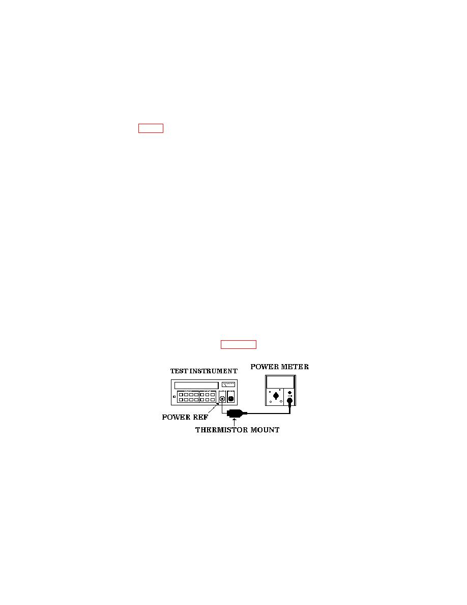
(7) Connect equipment as shown in figure 2.
(8) Set power meter LINE switch to ON position.
(9) Allow equipment and thermistor mount to warm up for 30 minutes before
proceeding to (10) below.
PIN: 071378-001
