
TB 9-6625-2317-40
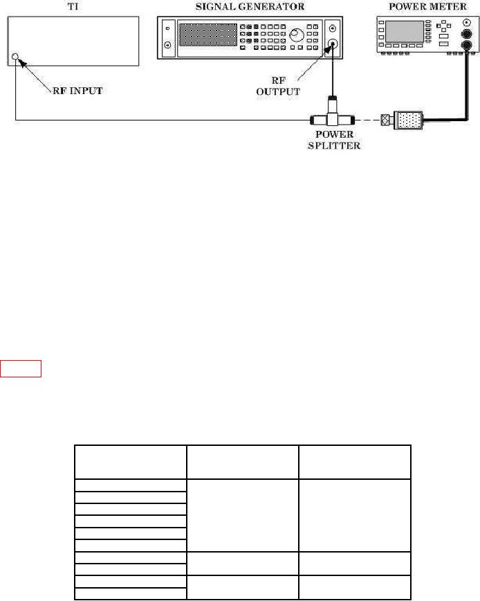
Figure 4. Input Sensitivity.
NOTE
On power meter, set frequency and cal factors accordingly.
(4) Press TI pushbuttons CARR FREQ, . (decimal), 6, 0, 0, & MHz.
(5) TI front panel FREQUENCY display will indicate 600 kHz RF and
LEVEL/DATA ENTRY display will indicate <-10 dBm RF.
NOTE
If FREQUENCY and LEVEL/DATA ENTRY display message
"RF input level low or off tune," proceed to troubleshooting
procedure.
(6) Repeat techniques of (3) through (5) above, using settings and indications in
table 6. TI front panel FREQUENCY and LEVEL/DATA ENTRY displays will indicate
frequency and RF level of input signal.
(7) Set signal generator output to off.
b. Adjustments. No adjustments can be made.
Table 6. Sensitivity.
Signal generator
Test instrument
frequency indication
Power meter indication
CARR FREQ
RF
(pushbuttons)
1
MHz
1 MHz
10
MHz
10 MHz
50
MHz
50 MHz
100
MHz
-25 dBm
100 MHz
200
MHz
200 MHz
400
MHz
400 MHz
600
MHz
-20 dBm
600 MHz
900
MHz
900 MHz
1.2 GHz
1200 MHz
1.6 GHz
-10 dBm
1600 MHz
9