
TB 9-6625-2317-40
b. Adjustments. No adjustments can be made.
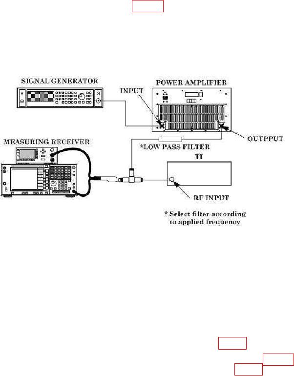
10. Input Power
a. Performance Check
(1) Connect equipment as shown in figure 3.
CAUTION
Due to the possibility of RF power amplifier spikes that may
cause equipment damage, reduce signal generator and RF
amplifier outputs to minimum when signal generator output
frequency is changed in the steps below.
Figure 3. Input Power.
(2) Configure measuring receiver for RF Power measurements.
(3) Ensure power amplifier output control is set to minimum and set signal
generator for a 10 MHz, minimum output.
(4) Slowly increase signal generator and amplifier output for a +10 dBm indication
on measuring receiver.
(5) Press TI pushbuttons CARR FREQ, 1, 0, & MHz.
(6) Press TI LEVEL DISPLAY RF POWER pushbutton (on). TI LEVEL/DATA
ENTRY display will indicate within limits specified in first row of table 4.
(7) Repeat technique of (3) through (6) above using settings in table 4.
TI
LEVEL/DATA ENTRY display will indicate within limits specified in table 4.