
TB 9-6625-2327-24
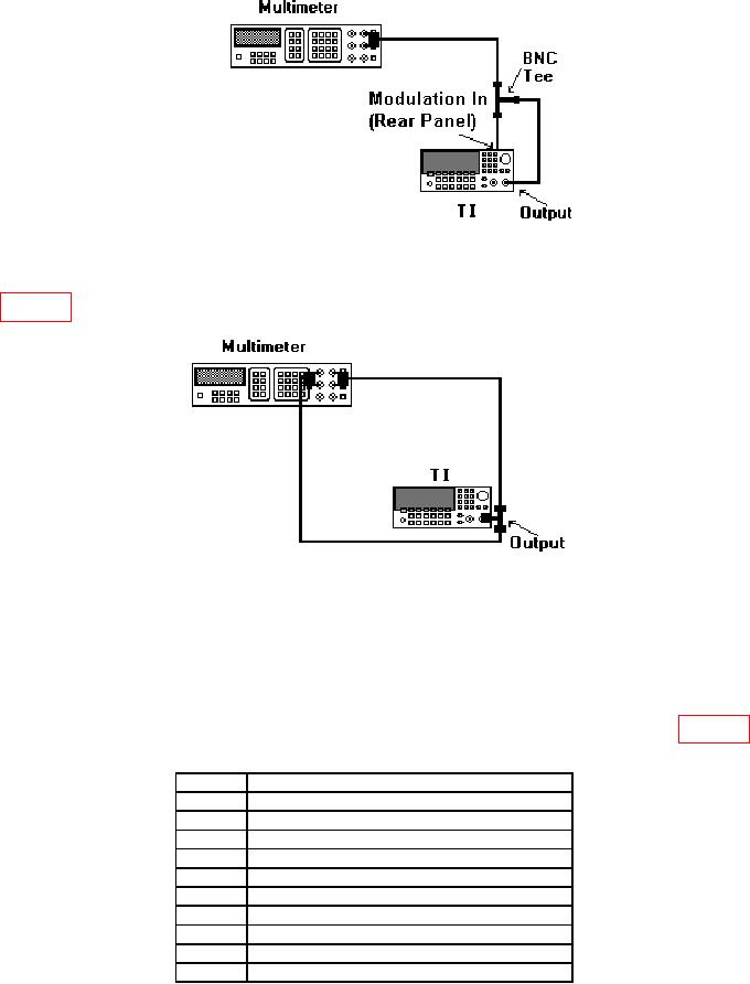
Figure 1. ADC Adjustment Hookup.
(10) Disconnect cable from rear panel Modulation In. Connect equipment as shown
in figure 2.
Figure 2. Output Impedance Adjustment Hook-Up.
(11) Set multimeter to measure offset-compensated, four-wire ohms, with 100 NPLC.
(12) When Setup # 7 is displayed press BEGIN key.
(13) Using numerical keypad, adjust displayed Meas'd Imped to match multimeter
indication. Press ENTER VALUE key, when values match.
(14) Repeat technique of (12) and (13) above for remaining parameters listed in table 14.
Table 14. Adjustment Setup #8 Through #17.
Step #
Typical test requirements
8
-30 dB range with distortion filter
9
-20 dB range with distortion filter
10
-10 dB range with distortion filter
11
0 dB range with distortion filter
12
+10 dB range with distortion filter
13
-30 dB range without distortion filter
14
-20 dB range without distortion filter
15
-10 dB range without distortion filter
16
0 dB range without distortion filter
17
+10 dB range without distortion filter
12